Archive for the 'CPU of the Day' Category

November 16th, 2015 ~ by admin

MHTL: Before the Processor

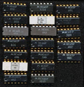
Motorola MHTL - Almost the entire product line is shown. Made from 1967-1972

Motorola MHTL – Almost the entire product line is shown. Made from 1967-1972

Before the single chip processor, the Intel 4004, TI TMS1000, or Four Phase AL-1 (depending on your school of thought) ‘processing’ was done by discrete logic.  These are SSI IC’s (Small Scale Integration), a step up from literal discrete transistors, each IC contains 2-30 transistors, implementing a couple gates.

The most famous of these is the TTL (Transistor-Transistor Logic) series developed by Sylvania in 1963.  Before TTL though their was RTL (Resistor-Transistor Logic) in 1961 and the next year, DTL (Diode-Transistor Logic), whereby Diodes were added to the inputs, allowing much better fan-in.  Neither of these designs had great noise immunity, which in many applications was very important.  Motorola patented a modification to DTL in 1966 with production of the new MHTL family commencing in 1967-1968.

MHTL, Motorola High Threshold Logic, was designed for environments where high noise immunity was a must.  Noise, really any voltage that is present, and not wanted/not an actual signal, can be complicated to deal with.  Motorola’s solution was to make the signal much larger, this s clearly the ‘bigger hammer’ approach to noise.  Normal DTL has a turn on voltage of 1.5V (0-5V Logic). fairly low, and in an industrial environment, where these IC’s may be controlling large motors and solenoids, a common noise voltage.  MHTL raised that to 7.5V, requiring a 15V supply.  Speed suffers greatly, as the voltage must now swing from 0-15V for a logic 0 to a logic 1 on the outputs, 3MHz being a typical max compared to 40MHz for Motorola’s DTL.  It should be noted, that as fast as that sounds, it’s only for a few gates, a full board of these will not be able to attain anything close to 3MHz due to propagation delays through the many IC’s.

The pictured MHTL devices are:

Device Function Transistors Power (mW)
MC660 Exp 4 Input NAND (Passive Pullup) 6 88
MC661 Exp 4 Input NAND (Active Pullupt) 4 88
MC662 Expandable 4-Input NAND Line Driver 6 180
MC663 Dual J-K Flipflop 24 200
MC665 Triple Level Translator (for interface to DTL, RTL or TTL) ?? 104
MC666 Triple Level Translator ?? 105
MC667 Dual monostable multi vibrator ?? 240
MC668 Quad 2-Input NAND Gate (Passive pullup) 8 176
MC670 Triple 3-Input NAND Gate (Passive pullup) 6 132
MC671 Triple 3-Input NAND Gate (Active pullup) 9 132
MC672 Quad 2-Input NAND Gate (Active pullup) 12 176
MC673 Dual 2-Input AND-OR-INVERT (Active pullup) ?? 160
MC675 Dual Pulse Stretcher/Multivibrator ?? 180

Today, noise immunity is still relevant, and much much more complex than simply increasing the supply voltage.  Higher supply voltages not only slow down switching, but they also increase power draw significantly. The MC660 pictured has exactly 2 gates (4-input NAND), consisting of 6 transistors, and still dissipates 88mW. That would be the equivalent of an Intel 4004 dissipating 12 Watts, or an Intel 386 needing about 4 Kilowatts. Modern noise immunity is handled by adding additional transistors (keepers, pre-chargers, etc) that can keep gates from being affected by noise, whether it’s from power/ground lines, leakages, or other reasons.  This allows chips with millions of transistors to operate at sub 1 Volt levels.  An impressive feat.

Tags:
, , ,

Posted in:
CPU of the Day

November 8th, 2015 ~ by admin

Sun UltraSPARC IIIi+: The Serrano

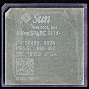
Sun UltraSPARC IIIi+ Early engineering sample from August of 2005

Sun UltraSPARC IIIi+ Early engineering sample from August of 2005

In early 2004 Sun Microsystems had a lot going on.  The UltraSPARC IV had been announced, and Sun was already talking about its upgrade, the UltraSPARC IV+.  Sun had recently released the Jalapeno, aka the UltraSPARC IIIi, their second processor with on die L2 cache (The first being the IIe designed for embedded use) in 2003. In 2002 Sun had purchased Afara Websystems for their SPARC design, known as Niagara, which became the Sun T1, and were working on its successor, the T2.  Both the T1 and the UltraSPARC V (the successor to the not even itself yet released IV) was scheduled to tape out the next year, yet itself was canceled in April of 2004, most of the entire engineering staff working on it is laid off.

At the same time Sun was talking up an upgrade for the lower end UltraSPARC IIIi, this would be a relatively simple process, more the existing core to a new process.  It currently was being made by TI on a 130nm 7-layer Cu interconnect process with low-k dielectric.  Moving it to TI’s 90nm process would allow for greater clock speeds, less power, and room on die to quadruple the L2 cache to 4MB.  The processor was code named Serrano, and widely announced as an upgrade to Sun’s Fire V215, V245 and V445 servers. Sun promised a release in late 2005. And then…

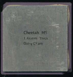
Sun UltraSPARC III Cheetah - Early Mechanical Sampele.

Sun UltraSPARC III Cheetah – Early Mechanical Sample. The IIIi added on die L2 cache

Nothing, talk of the Serrano went silent, all PR focus has shifted to the coming T1 and the UltraSPARC IV+. Both are released in 2005 to great applause, but the tech community is still wondering where the IIIi+ has gone?  Sun isn’t exactly forthcoming as to why, mentioning that it had been delayed in order to get the T1 out the door.  In mid-2006 a customer commented, “There have been problems getting the UltraSPARC IIIi+ processors, so the new systems will be released with the current chips.”  Finally in August of 2006 Sun come forward and says that the IIIi+ has been canceled, but there is a catch, it was canceled the year before, and Sun decided to just keep mum about it.

Keep in mind the IIIi+, other then the increase in L2 cache, was a fairly ‘routine’ port to a new process.  The delays, and cancellation at the time sounded like it was due to technical grounds, but looking back, and seeing that they had working silicon in 2005, it would seem that the decision to kill the Serrano was resource driven.  Likely a combination of Sun’s engineering and marketing constraints, as well as the availability of the 90nm process at TI, which was also being used for the Niagara.

Manufacturing capacity is a finite resource, so not using up what may have been a very limited amount of fab space, on a processor that was designed to slot into the low end servers, is possibly the best explanation we have for the cancelling of the UltraSPARC IIIi+, perhaps a former Sun engineer can fill in some more details, as so many of them were laid off whom had worked on Sun’s previous processors.  It was a gamble by Sun, and one which seems to have paid off, considering the success of the Niagara, though Sun/Oracle were far from done with canceling designs, Honeybee, Rock, and M4 all come to mind.

Posted in:
CPU of the Day
October 20th, 2015 ~ by admin

CPU of the Day: Military Signetics 8X305 Processor

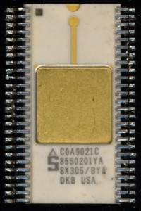
Signetics Military 8X305 - 1990 (8550201YA)

Signetics Military 8X305 – 1990 (8550201YA)

Some time ago we talked about the history of the Signetics 8X300 line of processors.  Originally released as the SMS300 in 1975 by SMS, the design was bought by Signetics.  It was a fairly unique 8-bit bipolar design, running at 8MHz. Its focus was signals processing, long before dedicated DSP’s such as the TI TMS320 came about.  The design was updated in 1982 to add some additional instructions and data handling.

Since it excelled so well at signals processing, the design worked well for military applications, where signals processing was of great use (interpreting data from a host of, usually, RF sensors.  The 8X305 was made in the normal 50 pin DIP, a 68 pin LCC, and an unusual 52 pin flat pack for military use.  In the 52-pin package the extra 2 pins are simply ‘No Connects’. (In the 68 pin version the extra 18 pins are divided amongst extra VCC, VR, GND, and N/C).

For military applications the greatest importance is on reliability.  This takes the form of three main areas:

Mechanical: How well can the design handle shocks, and vibrations, usually this is handled through better bonding wires, and more rigid package specs/inspection.
Electrical: How well can the device tolerate not great electrical conditions, higher reliability is achieved when the device can operate with a voltage that may very up to 10%, rather then the 5% or less commercial devices are designed to.
Temperature:  This is closely related to mechanical, as temperature stability requires the package to be damaged by expansion/contraction in wild temperature swings.  Obviously the silicon die itself needs to work with the same electrical characteristics at different ends of the temp range.  Many electrical parameters (such as resistance, and biasing) change over temperature, so the device must handle this. Typical military spec is -55C-125C (-67F-257F).  A range of 180C, from well below freezing, to well above boiling.

Venus - From the Mariner 10 Probe

Venus – From the Mariner 10 Probe

This Signetics 8X305 (Drawing # 8550201YA) is rated at -55-125C at 5V +/- 10% running at 8MHz.  It meets all the mechanical/inspection and testing requirements of MIL-STD-883 Class B.  This type of design work is well understood, and now a days, rather routine.  Making electronics work at 125C is no longer an engineering feat.  But then, what if we need more? Lots more.

Recently NASA contracted with Ozark Integrated Circuits to do just that.  NASA wants a process kit for IC’s that will run happily at 500C (932F) . At this temperature lead and tin have melted, and aluminum isn’t even very solid. If that sounds a bit inhospitable, you’d be right, and its exactly the conditions NASA faces with designing a rover for use on our nearest neighbor, Venus.

Ozark previously created such a process good for up to 350C, but thats still not hot enough for Venus.  Ozark is using a silicon carbide substrate, and some other proprietary methods.  They will not actually produce the chips for NASA, but rather licenses the methods to do so to a foundry service of NASA’s choosing, who will then manufacture and test them.

Surface of Venus, from Venera-13

Surface of Venus, from Venera-13

In the upper atmosphere, temps are below 0, and at the surface, atmospheric pressure is 90 times greater than on earth, another challenge for making a chip, with a die recessed in a sealed cavity.  Such requirements, and the technology to meet it, will greatly enhance our exploration abilities, and no doubt, trickle down in some way, to the electronics we use each day.

Posted in:
CPU of the Day
October 1st, 2015 ~ by admin

Western Digital and the COP

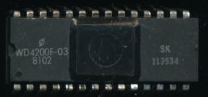
Western Digital WD4200F-03 - Copy of National COP420

Western Digital WD4200F-03 – Copy of National COP420 from 1981

In the 1970’s second sourcing was the name of the game.  Processors that had no additional source available often struggled in the market.  Designers wanted to ensure that if they invested in designing a product around a chip, that chip would remain available if the original manufacturer of it had issues.  It also helped drive down pricing, as often second sources could compete on price with the original manufacturer.

By the 1980’s second sourcing had begun to end.  It did still happen, but began to take the form of fabless semiconductor companies today.  A company would create a design and then license its manufacturing to other companies.

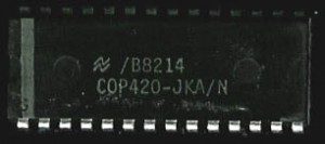
National Semiconductor COP420 - 1982

National Semiconductor COP420 – 1982

National Semiconductor was a popular second source for many processors of the 1970’s, notably Intel’s 8080, MCS-48 microcontrollers and AMD’s 2901.  For their own designs, they rarely second sourced to anyone.  Such designs as the PACE, SC/MP, original COPS and NSC800 were exclusive to National.  In the 1980’s they did have TI make a very limited amount of 32k processors, likely due to some of the reliability problems National was having in making them themselves early on.  So it is a bit surprising that they licensed the COPS II to Western Digital in the early 1980’s.

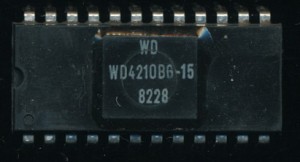
Western Digital WD4210BG-15 - Bond out option of the WD4200

Western Digital WD4210BG-15 – Bond out option of the WD4200

The COPS II (later just called COPS) was the 2nd generation COPS 4-bit microcomputer made by National.  It was a NMOS design, designed for basic control oriented applications to replace the PMOS COPs from 1976.  Western Digital already had the 4-bit CR1872 PMOS processor, as well as the CP1611 16-bit design.  Perhaps WD saw the COPS as a filler between those.  It certainly didn’t replace the CR1872, as that design continued to be marketed up until the mid-1980’s.

Western Digital made the WD4200 and WD4210 as copies of the National COP420 and COP421.  Also made was a WD4020 copy of the COP402 (the ROMLESS version used for dev work).  The WD4200 and WD4210 are nearly identical to each other.  The 4200 comes in a 28-pin package while the 4210 came in a 24-pin package.  WD (and National) called this a bond-out option.  The die is the same in both, the 4210 merely has one 4-bit input port left unconnected (IN0-IN3).  A 24-pin package was enough less expensive than a 28-pin package to make this a viable sales option.  Using a bulk NMOS process the die itself was a fairly insignificant cost compared to packaging and testing. The smaller package also was useful for smaller board designs.  The practice continues today with features on processors and MCU’s disabled/enabled to expand a product line and/or make use of die’s with defects.

WD continued to produce the COP line until at least 1983.  Western Digital was moving its focus to the storage market, and away from te general purpose processor/microcomputer market.  This brought an end to the WD4200 as well as WD’s other processors.   Today WD is known for hard drives, and remembered for their disk controllers. that they second sourced a 4-bit design from National has faded to the annuls of history.


September 6th, 2015 ~ by admin

The Electronika MK1 red3 PDP-11 Chipset and Tetris

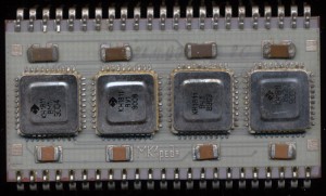
Soviet Electronika MK1red3 - F-11 Clone and implementation of PDP-11

Soviet Electronika MK1red3 – F-11 Clone and implementation of PDP-11

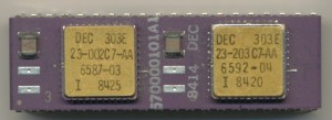
The DEC F-11 ‘Fonz’ implementation of the PDP-11 was released in 1979 and was DEC’s second ‘LSI’ implementation of the PDP.  Like its predecessor it was a multi-chip implementation, consisting at its root of a data chip (DC302) and 1-9 control chips (DC303).  The DC303 control chips were essentially a large ROM/PLA with a few extra features added for interrupts and sequencing.  They formed the microcoded instruction set that drove the 16-bit ALU and registers of the DC302.  This is why more then one were supported.  Expanding the instruction set was as ‘simple’ as adding more DC303 chips with these instructions encoded.  The basic LSI11/23 came with one 303 and one 302.  A second IC could be added to support floating point, which included a pair of DC303 chips implementing the floating point instructions.  A MMU (DC304) was also supported, and required when using the FP option.

DEC 570000101A1 F11 Floating Point Option with 2x 303E Control chips

DEC 570000101A1 F11 Floating Point Option with 2x 303E Control chips

The Soviets also widely adopted the PDP-11 architecture.  Likely because it was designed to be rather hardware independent.  It could be implemented in many different ways, which meant the Soviets could adopt/implement it on their own.  Electronika was part of the Soviet industrial complex in Voronezh, Russia making many different IC’s, but also was tasked with making consumer devices (computers and calculators etc, that were in very short supply.  The Electronika 60 was one of the first PDP-11 computers they made, and it implemented a copy of the DEC Fonz processor.  Electronika combined the standard chipset, and FPU onto a single large MCM with all 4 IC’s (the MMU remained separate) called the MK1 red1 (and later the MK1 red3)

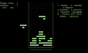
Tetris Electronika 60 - Text Only

Tetris Electronika 60 – Text Only

KH1811VM1 = DC302 – 21-15541 Data Chip (16-bit ALU etc)
KH1811VU1 = DC303 – 23-001C7 standard instruction set
KH1811VU2 = DC303 – 23-002C7 FP instruction set Part 1
KH1811VU3 = DC303 – 23-003C7 FP instruction set Part 2

It was on this chipset, on a Soviet Electronika 60 that Alexey Pajitnov wrote the very first version of the still famous game of Tetris back in 1984.  A game that was very popular, and very widely copied in the West, even to this day.  (the copying of technology most certainly went both ways)

Tags:
, , ,

Posted in:
CPU of the Day
July 26th, 2015 ~ by admin

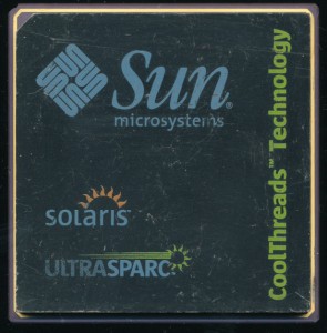
Sun CoolThreads UltraSPARC T1 Sample

Sun UltraSPARC TI Marketing Sample

Sun UltraSPARC TI Marketing Sample

The Sun UltraSPARC IV consumed 105 Watts at 1350 MHz.  This for a dual core processor that could process 2 threads.  Sun decided that the T1 (aka the Niagra) was going to change that.  It was the first ground up redesign of the SPARC core since the UltraSPARC III.  Interestingly Sun originally first attempted to develop a multithreaded process by using a pair of UltraSPARC II cores on a single die.  That project was canceled in 2004, as the T1 was in development.

The T1 was designed to focus on maximum processor utilization.  It contained up to 8 cores, each of which could process 4 threads.  This allows the processor to be used more efficiently, as a single thread can not slow down the entire processor.  All 8 cores share a single Floating Point unit.  This worked well for most database type processing, as FP instructions are not very common in that type of computing.  The T2 (made on a smaller process) allowed for a FP unit for each core which allowed better performance in HPC applications.

Made by TI on a 90nm process, the T1’s 279 million transistors consume only 72 Watts, a 30% reduction from the UltraSPARC IV at a similar clock speed.  This is what Sun called CoolThreads Technology.  Released in November of 2005 Sun was a bit ahead of their time, lower power, more efficient processors were only just beginning to become an important selling point.  Interestingly, its sister project, the UltraSPARC Rk, turned out to be not so cool.  Today, 10 years later, energy efficiency is one of the key metrics when measuring processor performance.  With data centers having on average 50,000 computers, 30 Watts per chip adds up, quick.

Tags:
,

Posted in:
CPU of the Day
July 16th, 2015 ~ by admin

TI SN74LS481: A Better Bit-Slicer

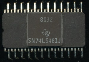
TI SN74LS481J -1980 - 8 MHZ 4-bit Slice

TI SN74LS481J -1980 – 8 MHZ 4-bit Slice

The 1970’s was a rush to design new and innovative processors, faster, more features, and more bits.  Most of the processors were new designs, a few were single chip implementations of older mainframes (such as the TMS9900 and the Intersil 6100.  At the same time there was a competition of 4-bit processors.  Somewhat remarkable in 1976 considering 16-bit designs were now being released.  The most famous was of course the AMD AM2901, which undoubtable won the battle.  There were others, the MMI 6701 (a company which AMD would go on to merge with).  Motorola had the MC10800, made in ECL and Intel made the ill-fated (probably since it was only 2-bits) Intel 3002 Processor.  TI made the SBP0400 in I2L that enjoyed some success, but that apparently wasn’t enough.  In 1976, the same year as the SBP0400, the 6701 and the AMD AM2901, TI released the SN74S481.  This was a Schottky TTL 4-bit slice processor (and the SN74S482 sequencer for it).  It was a bit different than its competition.

Read More »

Posted in:
CPU of the Day
June 11th, 2015 ~ by admin

Dallas: Reaffirming the Viability of the 8-bit Processor

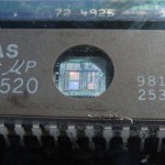
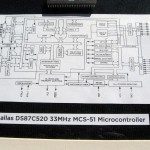
The introduction of the Dallas Semiconductor DS87C520 reaffirms the viability of 8-bit processors for new and demanding applications.  Those were the words written about the the Dallas DS87C520 (and its ROMLess version the DS80C320) in 1994. The Intel MCS-51 architecture it was based on had been released 13 years prior, in 1981 and ran at up to 12MHz.  By 1994 the Pentium had been released, with speeds of up to 100MHz.  Full 64-bit processors were also available, yet the 8-bit processor continued to hold on, and grow.

Dallas Semi. was founded in 1984, by former Mostek employees.  Their first products were lithium battery backed SRAMs, a product pioneered by Mostek.  Dallas added power saving and sensing circuitry to them though, greatly enhancing their usefulness.  In 1987 they combined with with an MCS-51 microcontroller to make the DS5000, which ran at 16MHz and provided battery backed SRAM.

With the release of the DS87C520 in 1994 they redesigned the MCS-51 core, allowing it to complete a machine cycle in 4-clocks vs the original 12.  They were plugin compatible, providing a simple speed up for 8051 systems.  Max clock was also raised, to 33MHz as well as additional interrupts, 16K of EPROM, an extra 1KB of SRAM and many power saving features/modes.  Other companies (such at Philips, and Atmel) began to also make enhanced 8051s, including things such as Flash memory and expanded instructions/features.

Its now 2015, and the 87C520 continues to be made, as does hundreds of other MCS-51.  It was surprising in 1994 that the 8-bit processor continued to be viable, and perhaps to some, even more so, that 21 years later, it is still viable, and shows no signs of slowing down.  The recent push into the Internet-of-Things (IoT) market has 8-bit MCUs in Internet of Things yet again.  While many companies have marked numerous 16-bit and 32-bit designs as ‘a migration path from 8-bit’, that migration is yet to be seen.  There simply is no reason, no need, and no desire to plug a 32-bit processor in where an 8-bit processor, implemented in a few thousand transistors, will do nicely.


June 2nd, 2015 ~ by admin

MG80386SX: Pin counts: How low can you go?

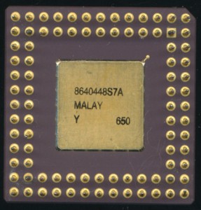
Intel MG80386SX16 in a 88-pin PGA

Intel MG80386SX16 in a 88-pin PGA

Seeing this pin out, the first processor that comes to mind probably isn’t an Intel 80386.  The 80386DX came in a 132 pin package (PGA or QFP) and the 386SX came in a 100 pin QFP.  The 386SX was the low end version of the 386.  It made do with 16 bits of Data bus, and 24 bits of Address, as opposed to the full 32-bit buses of the DX.  This accounts for 27 less pins (16 Data + 7 Address, 2 data byte selects and a 16/32 bit pin).  That covers all but 6 of the difference in package sizes.  Where are the rest from?  As with most processors, the signaling pins are not the only pins used, or not used on a package.

The 80386DX has 84 signal pins, pins that carry information to or from the processor.  It also has 40 pins for power and ground.  In the early days, when processors had only 40 pins or less, it made sense, and was feasible to have a single power and ground for the entire chip.  As complexities increased, routing became harder, and it became easier to have multiple power and ground pins to the die.  Not to mention electrically more stable, as current requirements were also increasing.  In addition the 386DX has 8 pins not used at all.  These are known as ‘No Connects.’  They are reserved for future use, or were there for testing, or simply just not needed.

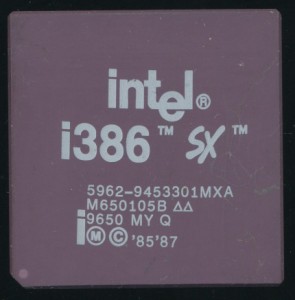
Intel 5962-9453301MXA MG80386SX16 - 16MHz 80386SX - 1996 Full Milspec

Intel 5962-9453301MXA MG80386SX16 – 16MHz 80386SX – 1996 Full Milspec

Moving to the 386SX, which has 26 less signal pins (58), the standard 100 pin package used 10 No Connects and the rest (32) for power and ground.  The pictured 386SX is a late production (1996) military spec processor in an 88 pin package.  88 pins still leave plenty (30 pins) for power, ground, and no connects.  The PGA 386SX was only produced for military/industrial uses.

Why use an expensive PGA package on a low end SX processor?  The reduced bus sizes were plenty for many industrial applications while the ceramic package was much more reliable, and mechanically strong when soldered on to a board then a plastic QFP.  The PGA could work over the entire military specification, for temperature, voltage etc.  Its likely the 386SX could run on an even smaller pin count, but the PGA88 package was a standard package already in production, which often dictates how many pins a processor will have.  The same is true today, pin-count is usually driven more by what works for the package, then what the processor actually strictly needs.

Posted in:
CPU of the Day
May 20th, 2015 ~ by admin

TI TMS7000: The SCAT Microcontroller

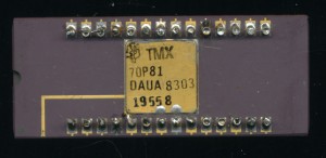
TI TMX70P81 - Early 8K Prototype. Never released

TI TMX70P81 – Early 8K Piggyback Prototype. Never released

The 1980’s brought many 8-bit microcontrollers to the market, such famous designs as the Intel MCS-51, the Zilog Z8, and the Motorola MC680x.  There were many others as well, including TI’s entry into the market.  After the race into the market with one of the first microcomputers, the 4-bit TMS1000, and the top of the line TMS9900 16-bit processor, TI saw the need to fill in the middle, the 8-bit market.  TI didn’t want to make the 7000 series just another 8-bit MCU either, they wanted something different, not so different as to be eccentric, but something to set them apart.  They did so with an innovation they called SCAT.

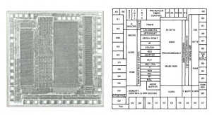
TMS7000 SCAT Layout. Notice the 'strips' that form the different sections of the MCU (click to enlarge)

TMS7020 (2K EPROM + 128 bytes RAM) SCAT Layout. Notice the ‘strips’ that form the different sections of the MCU (click to enlarge)

SCAT, Strip Chip Architecture Topology, was TI’s die layout design for the TMS7000.  Instead of generating each of the blocks for the chip (SLU, ROM, RAM, etc) making them as small as possible, and then using random logic to tie them all together, they laid them out in strips on the die.  The ROM in a strip, the RAM in a strip, and the ALU etc in another.  This allowed the sections to be wired up with a minimum of random logic, resulting in a smaller die, that was also easier to test.  More importantly it allowed the TMS7000 to be easily expanded.  Adding more ROM, or RAM didn’t require redoing the entire layout, it was just added to its respective ‘strip’.

Read More »

Posted in:
CPU of the Day