August 14th, 2019 ~ by admin

How to 386 Your AT: Intel Inboard 386/AT

With the release of the 32-bit Intel 386 processor in 1986, owners of IBM PC/XT and AT type systems (8088 and 80286 systems) were left a bit in the dust.  This was a concern (or opportunity) for Intel as well. They designed an upgrade solution at the same time as the 386, to be able to be used in the now obsolete computers.  This was the Intel InBoard 386 series of upgrade cards.

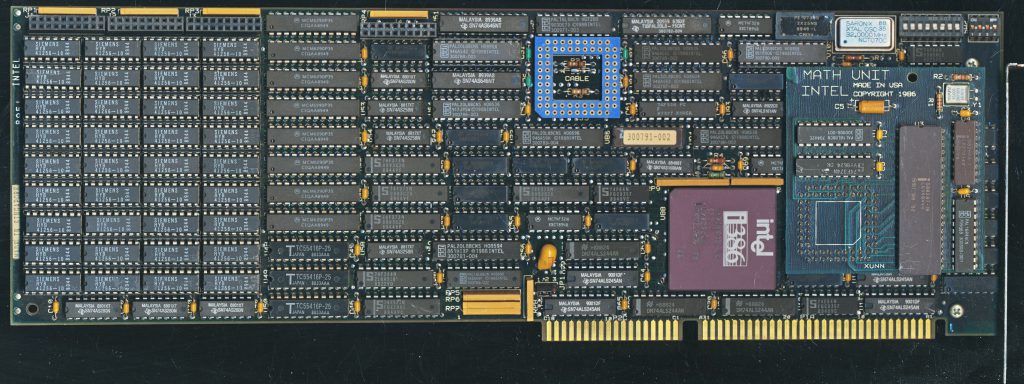
InBoard 386 AT with 1MB of RAM and 80287 FPU Option (very unusualy on a late model Inboard, this one from 1990, but the FPU is from 1986)

The InBoard, as its name implies, was a internal 16-bit ISA card that was used to upgrade these systems.  It included a 386DX processor running at 16MHz, 64K of cache, and (optionally) 1-3MB of additional RAM.  Two version of the board were made: the PC/XT version was designed for 8088 processor based systems, and the AT version was for the 286 systems.  These boards required the removal of the original processor, and then a cable was ran from the old CPU socket, to the the InBoard 386 board.  On system start up the original BIOS booted the system, and loaded the DOS operating system.  The config.sys file would then call on the drivers to load the InBoard 386 specific features.  The original system was essentially unaware of the new processor, instructions were executed by the InBoard transparently.

Flat Ribbon Cable used for connecting the board to the old CPU socket. If the cable could not reach the socket, your system was not compatible. Cable length was restricted by signal timing, rather then the common complaint of Intel being ‘stingy’

Early AT systems used a 6MHz CPU and ISA bus speed, so Intel provided a 8MHz crystal to replace the original on the motherboard. This ensured the ISA bus that the InBoard used to communicate with the original memory and peripherals ran fast enough and did not become such a huge bottle neck.   The base model InBoard did not come with any RAM, it could use your existing system RAM just fine.  Adding RAM, however, was a worthwhile upgrade.  The Board itself supports 1M (36 100ns 256 kbit chips, including parity) and a daughter card could add another 1M or 2M.  This RAM was accessed via the 80386s 32-bit address bus so was much quicker.  It also was a single wait state access.  You could configure the InBoard to backfill (take over for) your existing system RAM, at least down to 256K, so that the computer would only use the first 256K of the slower RAM before moving to the RAM on the InBoard.  If your system had 512K of RAM you would ‘waste’ half of it but at the benefit of much faster access times.  The Inboard 386 had another trick up its sleeve to improve speed…

Read More »

Posted in:
Boards and Systems

June 12th, 2019 ~ by admin

Xeon Overclocking: Making Gallatin Gallop

This article is part of The CPU Shack’s continued partnership with guest author max1024, hailing from Belarus. I have provided some minor edits/tweaks in the translation from Belorussian to English.

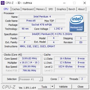
If you still remember the times of the Pentium 4 running on Socket 478 with the Northwood, Prescott and Gallatin cores, then you should remember what about these processor cores were different from each other. Northwood was fast like a mountain doe due to a shorter 20-stage pipeline that allowed it to perform many operations very quickly without tremendous losses due to branch mis-predictions etc. , but inferior to Prescott frequency potential in overclocking, which in turn was as strong as a buffalo, due to twice the L2 cache memory(1M vs 512K) and finer tech process (90nm vs 130nm). But like any hoofed animal, it was not agile, to achieve the higher clock speeds its pipeline was extended to 31-stages, resulting in some cases, clock for clock out performing Northwood, But doing so at the expense of much heat.

A separate niche in the food chain was occupied by “Gallatin”, which combined the properties of the two previous iterations, a shorter 20-stage pipeline, with the high clock speed of the Prescott, but in its arsenal it also had a very formidable weapon, which was the presence of an additional L3 cache of 2 MB. The price of ownership of this “beast” was high, and in the literal sense of the word, it was equal, like any other representative of the Extreme Edition series – $ 999. I resisted this extreme processor, choosing  hero from AMD, the FX-51, which I consider to be one of the most outstanding processors of all times and peoples.

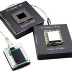
Xeon Universal Chip Analyzer by x86.fr

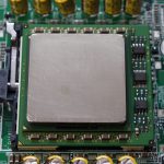
What could be better, cooler or faster? I’ve been looking for an answer to this question for a long time, until I became acquainted with the Intel Xeon server processors on Socket 604 and in particular with processors based on the Prescott 2M core, which have twice the cache size compared to their desktop counterparts and can run on ASUS production boards.

As everybody knows, it is the advanced desktop flagships of both processor manufacturers that originate from the server segment. So from the Opteron’s turned out the AMD Athlon FX-51, and from the Intel Xeon MP – the Pentium Extreme Edition. This parity of events has been preserved until now.

Xeon Gallatin MP

The server representatives of Intel Xeon processors on the Gallatin core are divided into two branches: Xeon MP (Gallatin) and simply Xeon (Gallatin). The differences are in the number of simultaneously supported processors in the system. So Xeon MP supported running up to four processors  usual Xeon could be installed in servers only in pairs. There is also a difference in steppings of the processor core itself. Let me remind you that the desktop version of “Gallatin” were the M0 stepping, just like the regular Intel Xeon series.

The Xeon MP line, by contrast, is based on an earlier stepping from A0 to C0. Among the representatives of M0 stepping, you can find four Xeon models (Gallatin) with 1M of L3 cache, with frequencies from 2.4 GHz to 3.2 GHz, and one model with a doubled  L3 cache to 2 MB, pretty much the same as a Pentium 4 Extreme Edition. This model gave rise to the first “extreme” Pentium.

Read More »

June 1st, 2019 ~ by admin

All Boxed up: Retail Boxed CPU’s

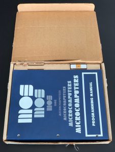
NIB MOS 6502 CPU

New In Box MOS MCS6502 CPU from 1975 (Michael Steil – pagetable.com)

Today most all processors are permanently installed in their device (soldered in) or were taken from a bulk tray and installed by the OEM such as Dell or HP.  AMD has, at least with their higher end CPU’s gotten quite creative with the marking on the chip itself, and both AMD and Intel still offer some pretty amazing retail packaging for their enthusiast processors (the i9 in a dodecahedron package is pretty cool).  There was a time when almost all processors were available in retail packaging.  This was the time of physical computer shops, largely bypassed now by the Internet, where the packaging of a processor helped sell it.

I collect such New In Box (NIB) processors as they are pretty need to see the branding/marketing that went with the CPU’s of years past, and was reminded of this when I saw perhaps one of the oldest NIB CPU’s I have ever seen on Michael Steil’s pagetable.com blog.  An original MOS 6502 processor from 1975 in its original shipping box, as close to NIB as one can get.  MOS’s packaging would make Apple proud with its simplicity and design keeping everything tidy and the MCS6502 visible as soon as the box is opened (I am happy they didn’t use miserable black foam either, so the CPU is pristine after 45 years).  Even the original invoice is included.  $25 for the CPU ($118 in 2019 dollars) and $10 (nearly half the cost of the CPU ($47 in 2019)) for documentation)

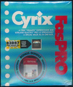
Cyrix 83D87 386 FPU

Cyrix 83D87 386 FPU Bundled with Borland Quattro PRO Spreadsheet software (a big thing back in 1992)

Intel started offering retail boxed CPUs with the 8087 coprocessor.  This was really the first chip designed as a user upgrade to their PC (a new thing back then).  Before this Intel’s closest thing to a NOB was University Kits or Dev Kits for various chips/processors.  With the introduction of the PC, and the many thousands of beige box clones that followed, people themselves began buying processors and building computers for themselves at a much greater pace then before.  There was many companies making compatible processors at the time so packaging helped set them apart.  This began with upgrade products, math coprocessors for the 808x, 286 and 386 were the most common (by Intel, AMD, IIT, ULSI. Cyrix and more), but eventually processors themselves started getting the NIB treatment, Intel made OverDrive processors (still technically an upgrade product) for the 486. followed by actual Pentium CPUs in the retail box. By the late 1990’s everything from Celerons to Xeon server processors could be had in Retail box.  Buying a retail boxed Xeon for your rackmount server seems like an odd thing to do, but apparently Intel figured it would need to be done.

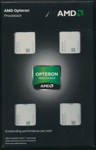
Quad AMD Opteron 6128s in Retail Box

Quad AMD Opteron 6128s in Retail Box

Other companies such as AMD, Cyrix and VIA made NIB processors but they are much less common, and in a lot of ways more interesting.  AMD made retail Durons, Athlons, and Opterons, and in one of the most unusual things I have seen for a NIB, an actual 4-pack of Opteron 6128s (pictured). The Opteron 6128 is a 8 core Magny-Cours server processor introduced in 2009 and cost $266 each at that time.  This NIB set is dated late 2011, so would probably be a bit cheaper, but still $800 or so, and the large SWATX motherboards needed to run 4 socket G34 processors require somewhat special cases and PSU’s, but at least you can have  a half terabyte of RAM.  Inside the retail box is 4 smaller boxes, each containing an Opteron 6128 CPU, installation instructions, warranty info, and a case badge (you get 4 total case badges).  It seems this packaging was designed to support different configurations (probable a single Opteron 6128, and duals).

Tags:
, ,

Posted in:
CPU of the Day

April 18th, 2019 ~ by admin

Tiered up for 3D-FPGAs: The Story of the Tier Logic FPGA-ASIC

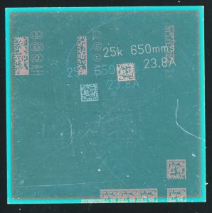
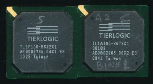
100K LUT Tier Logic FPGA TL1F100 on the left and TL1A100 ASIC on the right

This is the CPU Shack Museum, but occasionally I find a chip thats not really a CPU but is of such interest that I keep it, especially if its novel and relatively unknown.  So today we have a bit of the story of Tier Logic.  Tier Logic set out to make FPGA (Field Programmable Gate Arrays) better, and to make the transition (or choice) between them and ASICs (Application Specific Integrated Circuit) easier.

FPGA’s are great for smaller product runs, they are configurable, and relatively easy to reprogram, designs can easily be updated/tested with no additional cost.  FPGA’s however are large in terms of die area, power budgets, and cost per chip.  ASIC’s on the other hand, take longer to develop (re-spinning silicon every time an error is found) and have a much larger upfront cost, as well as an entirely different tool chain to design with. They are however smaller, use less power, and once the design is finalized, the per unit cost is very low.  This presents a dilemma in design, which should one choose for a project?  What if you didn’t have to choose? What if you could have the flexibility of an FPGA, and the benefits of an ASIC all at once?

It is exactly this that Tier Logic set out to do.  Tier Logic was founded by FPGA process-technology pioneer Raminda Madurawe (from Altera) in 2003 and was led by Doug Laird, a founder of Transmeta (famous for the Crusoe VLIW processors).  For 7 years they worked to design a solution, working in what is known as ‘stealth mode.’  Stealth mode is a way for companies to work quietly, with little to know PR, until they have a product ready to release.  Often the company exists but is completely unknown to outsiders.  This has some definite benefits, there is no constant barrage of having to answer/report to the media and others, and their is less risk of someone seeing what you are doing and trying to beat you to market to it.  Seven years, however, is a very long time to be in stealth mode, and the reason for this is Tier Logic not only was inventing a new style of FPGA/ASIC, they had to develop a new silicon process to make it work.

Read More »

Tags:

Posted in:
CPU of the Day

March 31st, 2019 ~ by admin

CPU of the Day: CS603RMP-200 PowerPC 603r Goes Golden

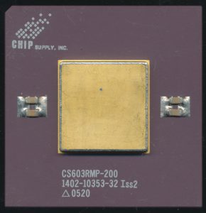
Chip Supply Inc. CS603RMP-200 – 2005 Production Miltemp PowerPC 603r

The original PowerPC 603 was released way back in 1994, made on a 0.5u process and running at 75MHz.  A year later, the greatly improved PowerPC 603e was released, made on the same process, but supporting speeds of up to 200MHz.  It doubled the L1 caches to 16K each (for Instruction and Data) and introduced some Power Down modes useful for mobile and other low power applications.  A die shrink to 0.5u allowed speeds of up to 300MHz.

The 603e was available in both BGA  and cerquad packages, which worked for most applications.  But what if you wanted something a bit different?  What if your application needed something a bit more robust.  This is where packaging and die specialist companies come into play.  Motorola/IBM had no desire to make short runs of oddball packages and/or dies screened for higher end use.  Other companies however, did…

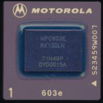
Motorola MPC603ERX100LN – 2000 vintage PowerPC 603e

Chip Supply Inc. was founded back in 1978 in Orlando, FL  just for this purpose.  Chip Supply provided die testing and packaging services for many different companies.  They also provided a service known as ‘die banking’ and just as the name implies, this involves collection and storing wafers and/or dies for future use.  This helped with end-of-life products especially.  As manufacturers slowed, changed, or stopped production of a device, dies for it could be made available through firms like Chip Supply.

In 1997 Chip Supply Inc. signed an agreement with Motorola giving them access to bare dies and known good dies for the PowerPC 603e, MPC106/7 PCI Bridge, and the MC68000 line.  This allowed Chip Supply to source dies from Motorola, screen them for higher spec (Military and Industrial temp typically).  Motorola had a similar agreement with Thomson-CSF (later this line was acquired by Atmel) who did the same thing, but also made radiation tested parts for space use (notably used on the original Iridium satellite constellation).

16×16 PGA in a 50mm package. Pins are 6mm long (twice as long as a Socket 7 Pentium)

The CS603RMP-200 is a 200MHz PowerPC 603r processor.  The 603r is nearly identical to the 603e, but allows for lower voltages (2.5V) and is made on a 0.29u process.  Chip Supply packaged this in a 16×16 CPGA package that is 50mmx50mm (nearly 2 inches square). It includes a large, gold plated heatspreader thats about the same size as a typical BGA PowerPC 603e.  These use original Motorola dies, upcreened to Military temperature (-55-125C) and tested to run at 200MHz.  The large heatspreader and ceramic package allow for better thermal management, and better mechanical support.  Thermal cycling and vibrations often result in BGA connection failures (a familiar problem on some game consoles in the early 2000’s), something a properly mounted PGA chip is much more tolerant of.

Chip Supply Inc. was acquired by Micross Components in 2010, a company that formed in 1998, and provided the same services with the addition of radiation testing. It appears that this was the end of the line for the entire PowerPC line by Chip Supply, though its likely that custom orders could be fulfilled for sometime after the acquisition.   Someday perhaps we’ll find out what applications the PGA PowerPC 603s were used in.

Posted in:
CPU of the Day

March 1st, 2019 ~ by admin

CPU of the Day: UTMC UT69R000: The RISC with a Trick

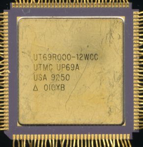
UTMC UT69R000-12WCC 12MHz 16-bit RISC -1992

We have previously covered several MIL-STD-1750A compatible processors as well as the history and design of them.  As a reminder the 1750A standard is an Instruction Set Architecture, specifying exactly what instructions the processor must support, and how it should process interrupts etc.  It is agnostic, meaning it doesn’t care. how that ISA is implemented, a designers can implement the design in CMOS, NMOS, Bipolar, or anything else needed to meet the physical needs, as long as it can process 1750A instructions.

Today we are going to look at the result of that by looking at a processor that ISN’T a 1750A design.  That processor is a 16-bit RISC processor originally made by UTMC (United Technologies Microelectronics Center).  UTMC was based in Colorado Springs, CO, and originally was formed to bring a semiconductor arm to United Technology, including their acquisition of Mostek, which later was sold to Thomson of France. After selling Mostek, UTMC focussed on the military/high reliability marked, making many ASICs and radhard parts including MIL-STD-1553 bus products and 1750A processors.  The UT69R000 was designed in the late 1980’s for use in military and space applications and is a fairly classic RISC design with 20 16-bit registers, a 32-bit Accumulator, a 64K data space and a 1M address space.  Internally it is built around a 32-bit ALU and can process instructions in 2 clock cycles, resulting in 8MIPS at 16MHz.  The 69R000 is built on a 1.5u twin-well CMOS process that is designed to be radiation hardened (this isn’t your normal PC processor afterall).  In 1998 UTMC sold its microelectronics division to Aeroflex, and today, it is part of the English company Cobham.

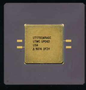
UTMC UT1750AR – 1990 RISC based 1750A Emulation

UTMC also made a 1750A processor, known as the UT1750AR, and if you might wonder why the ‘R’ is added at the end.  The ‘R’ denotes that this 1750A has a RISC mode available.  If the M1750 pin is tied high, the processor works as a 1750A processor, tied low, it runs in 16-bit RISC mode.  How is this possible? Because the UT1750AR is a UT69R000 processor internally.  Its the same die inside the package, and the pinout is almost the same (internally it may be but that’s hard to tell).  In order for the UT1750AR to work as a 1750A it needs an 8Kx16 external ROM.  This ROM (supplied by UTMC) includes translations from 1750A instructions to RISC macro-ops, not unlike how modern day processors handle x86.  The processor receives a 1750A instruction, passes it to the ROM for translation, and then processes the result in its native RISC instructions.   There is of course a performance penalty, processing code this way results in 1750A code execution rates of 0.8MIPS at 16MHz, a 90% performance hit over the native RISC.  For comparison sake, the Fairchild F9450 processor, also a 1750A compatible CPU, executes around 1.5MIPS at 20MHz (clock for clock, about 30% faster), and thats in a power hungry Bipolar process, so the RISC translation isn’t terrible for most uses.

NASA Aeronomy of Ice in the Mesosphere – Camera powered by RISC

By today’s standards, even of space based processors, the UT69R000 is a bit underpowered, but it still has found wide use in space applications.  Not as a main processor, but as a support processor, usually supporting equipment that needs to be always on, and always ready.  One of the more famous mission the UT69R000 served on was powering the twin uplink computers for the DAWN asteroid mission (which only this year ended).  It was also used on various instrumentation on the now retired Space Shuttles. The CPU also powered the camera system on the (also retired) Earth Observing-1 Satellite, taking stellar pictures of our planet for 16 years from 2000-2017.  Another user is the NASA AIM satellite that explores clouds at the edge of space, originally designed to last a couple years, its mission which started in 2007 is still going.  The

JAXA/ESA Hinode SOLAR-B Observatory

cameras providing the pretty pictures are powered by the UT69R000.  A JAXA/ESA mission known as SOLAR-B/Hinode is also still flying and running a Sun observing telescope powered by the little RISC processor.

There are many many more missions and uses of the UT69R000, finding them all is a bit tricky, as rarely does a processor like this get any of the press, its almost always the Command/Data Processor, these days things like the BAE RAD750, and LEON SPARC processors, but for many things in space, and on Earth, 16-bits its all the RISC you need.

January 24th, 2019 ~ by admin

Intel Everest Goes to Auction

Last summer we wrote about the Intel Everest series of high end CPU’s.  These are processors which Intel makes for very specific customers (in this case High Frequency stock trading).  They often have very little official information about them, and are sold at prices around $20,000 each. The latest in the series is the Intel Core i9-9990XE, with a max Turbo Frequency of 5.1GHz.  According to Anandtech, these will be auctioned off to the highest bidder.  These chips are a 14-core processor dissipating 255W, so will require rather good cooling, motherboard and Power Supply Support.  The chips will be auctioned to ‘select OEM’s’ once per quarter throughout 2019.  Intel isn’t likely deliberately making these chips scarce to increase the price, they are rather very rare speed bins for chips to attain.  Out of thousands of chip’s tested, only a few will pass screening at this level of performance.  These typically come from the center of a wafer (defects typically increase towards the edge of a wafer).  It will be interesting to see what prices these attain, but then again, we may never know.

Posted in:
CPU of the Day

January 18th, 2019 ~ by admin

Part 4: Mini-Mainframe at Home: Benchmarks and Overclocking

Part 4 of the Story of a 6-CPU Server from 1997.  In this final section we will first explore (briefly) the theory of running a 6-CPU SMP system (with processors designed for 2 or 4 way) and then move to benchmark the system and overclock it.

For the background of the ALR 6×6 and Pentium Pro processors that form the basis of this project please see:

Previous Parts of the Series

Part 1: Mini-Mainframe at Home – Introduction
Part 2: Mini-Mainframe at Home: Installing a Modern OS
Part 3: Mini-Mainframe at Home: The ALR 6×6 Hardware and BIOS

Features of the architecture and operation of the six CPU

So, as the server was originally shipped with six Pentium Pro “Black” processors, I decided to add six Pentium Pro “Gold” processors with a frequency of 200 MHz and a 256 KB L2 cache for contrast. Such a volume is just four times smaller, and at the same time it will be interesting to check the effect of the cache in such a volume: six megabytes versus one and a half.  But before starting the tests, I will focus on the principle of interaction of six processors in this system. To overcome the limitations of Intel on building a system with more than four processors, ALR engineers with the support of Unisys suggested using an inter-processor interaction scheme using arbitration:

The theory behind this architecture is as simple as it is powerful. Inside new six-way systems are two Tri-6 CPU cards, A and B (Figure 1). Each of these cards is an independent, three processor ready SMP bus, complete with all logic Active CPR processor protection, and auto-recovery technology built on each CPU card. These two Tri-6 CPU cards are then plugged into a 64-bit parity SMP bus. This design keeps the processors closely coupled, just like a parallel bus architecture, without the related heat and design problems. A separate four-way interleaved memory card is attached to the bus, supporting a sustained data bandwidth of 533-MB per second. This bandwidth is ample to support two full PCI buses as well as an EISA bus bridge.

To overcome the logical limitations of the Pentium Pro chip, six-way servers use a unique expanded bus arbitration configuration referred to as Dynamic Orchestration. The best way to understand how this system works is to compare it to a typical four-way SMP architecture. On a four-way system, bus arbitration is implemented in a “round robin” fashion. That is, each processor has equal rights to the bus, and access is handled in an orderly fashion. For example, if all processors needed access to the bus, CPU 0 would gain access first, followed by CPU 1, CPU 2, CPU 3, and then back to CPU 0. If CPU 2 was executing a cycle, and both CPU 3 and CPU 1 requested use of the bus, control would first pass to CPU 3, before cycling back to CPU 1.

For purposes of this four-way arbitration, processors are identified using the two-bit ID code. The six-way solution borrows this convention, with some important modifications. Within each Tri6 CPU card, individual processors are identified using the two-bit ID code. This yields four possible combinations, although only ID codes 0 through 2 are needed. A chip on each Tri6 card handles the arbitration, following the “round robin” scheme found in a four-way system. In this case, however, the fourth processor has been replaced by a sort of “phantom” processor that actually represents the other Tri6 card:

The figure above shows the six-processor scheme of the server board ALR Revolution 6×6 and its clones. Thanks to this approach, the appearance of 8, 10 and more processor systems has become possible.

Building a chessboard from various models of Pentium Pro, I thought that I could not find a larger processor. Even the 32-core AMD Threadripper 2990WX next to the Intel Pentium Pro does not seem so big.

However, The CPU Shack sent me this photo. On the left is the engineering version of the Xeon Gold 6142 on the LGA3647 socket, on the right another engineering version, but already the Intel Xeon’a Phi in the same LGA3647 version. As you can see, the story is back to square one and perhaps all subsequent processors will not be placed on the open palm of the hand. Although the processors in the performance of LGA2066 is still far from Intel Pentium Pro.

Overclocking 6 cores together and separately

Read More »

Posted in:
Boards and Systems

January 16th, 2019 ~ by admin

Part 3: Mini-Mainframe at Home: The ALR 6×6 Hardware and BIOS

Part 3 of The Story of a 6 CPU Server from 1997 – In this section we’ll learn about the hardware and BIOS that makes the ALR Revolution 6×6 with 6 Pentium Pro Processors work.

For the background of the ALR 6×6 and Pentium Pro processors that form the basis of this project please see:

Part 1: Mini-Mainframe at Home – Introduction
Part 2: Mini-Mainframe at Home: Installing a Modern OS

Exterior and Interior

The size of the case is quite large for the desktop (and it came with wheels, so probably not good  to have rolling about ones desk), but relatively compact for servers of this class. The height of the server is – 68 cm, width – 32 cm and depth – 58 cm. The weight of the server starts from 52 kg. I have a complete server kit, but the case is missing, because, due to its size and weight, the shipping to Belarus would be around $ 400, if not more, so the photos of the appearance were taken from the Internet.
Editor’s Note: The empty case is currently serving as a kitchen counter at the CPU Shack Museum.  Its really THAT big 

The first thing that catches the eye is the information touch! LCD display, the task of which is to display all the information about the status of the six processors, RAM, temperature, status of hard drives and other vital information. Today, such informative displays are the norm, but 21 years ago I even could not imagine that such a thing ever happened. The front of the case also has two compartments, the upper one under 5.25” devices, such as CD-ROM’s, the lower one opened access to the cage with SCSI drives. Behind you can see 14 expansion slots, a cooling system and a cage with power supplies.

To ensure the operation of  the server, two power supplies are needed, which are connected to a special board in the cage. The third power supply unit is a spare one in case of a single power supply failure. It is allowed to install four power supplies with the connection of two pairs to a pair of electrical outlets for complete duplication of all functions providing the server power.

Read More »

Posted in:
Boards and Systems

January 14th, 2019 ~ by admin

Part 2: Mini-Mainframe at Home: Installing a Modern OS

Part 2 of The Story of a 6 CPU Server from 1997 – In this section we’ll try to get a modern OS running on the ALR Revolution 6×6 with 6 Pentium Pro Processors.

For the background of the ALR 6×6 and Pentium Pro processors that form the basis of this project please see Part 1 of the project.

Part 2: Installing and Using an OS

Before you start installing the OS, you need to select the correct kernel of the operating system. To do this, at the initial stage of installation, press the F5 key.

In this case, we choose – MPS Multiprocessor PC, since the other options simply do not fit, since this server naturally does not support ACPI. In general, I will advise anyone who makes such experiments by choosing a more “modern” OS, which is older than the hardware itself – to turn off ACPI support in the BIOS (if present). This simple action will keep your nerves decent.

Windows Server 2003 R2 Enterprise Edition was installed and, as I wrote above, the system had one working CPU core.

Next, an attempt was made to install the operating system from the operating system itself using the update method, but at the initial stage the Windows Server 2003 Enterprise Edition installer warned me that a multiprocessor configuration not supported by the operating system was used.

But there are many ways to install the OS. Alternatively, I tried the OS “transfer method” with a known-workable SMP configuration. Taking the ASUS P2L97-DS motherboard on an Intel 440LX chipset with a pair of Intel Pentium-II with a frequency of 450 MHz, which should be deprived of a hardware error and chose the “MPS Multiprocessor PC” core, but the installation process did not start at the stage of copying the original files, reaching until installation on the hard disk. At this point, the system hung, not reaching the choice of the installation source. Much has been tried, loops, different drives and RAM, but all to no avail. At this point, a single Pentium-3 was also hanging on the Asus P3B-F motherboard (Intel 440BX chipset).

In the end, I decided to take another board with two SLOT 1 connectors – Asus P2B-D (Intel 440BX chipset) and a pair of Intel Pentium-III. OS Windows Server 2003 R2 Enterprise Edition was safely installed, it remains to transfer it to a six-processor server. As a result, having moved the necessary hard drive, I decided to do the first boot in “safe mode” in order to exclude the influence of different devices of both systems on each other, but as a result I received a BSOD.

Read More »

Posted in:
Boards and Systems