November 20th, 2021 ~ by admin

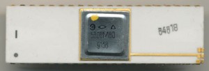
The Soviet 1801VM3 Enhanced LSI-11 Processor

This is turning into a bit of a series on Soviet processors.  Continuing from our article earlier on the 1801VM2 LSI-11.  The 1801VM3 is the further development of 1801VM1/VM2 and is the highest performance microprocessor in 1801 series. It’s a 16-bit single-chip microprocessor that includes an operating unit, a firmware control unit, an interrupt unit, a memory controller and Q-BUS control unit. A distinctive feature of 1801VM3 is a large amount of addressable memory (4MB vs 64K for the 1801VM1 and 64k+64K for the VM2), high performance and ability to connect a floating-point coprocessor 1801VM4.

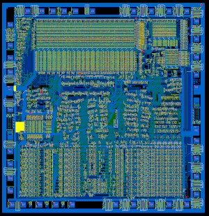
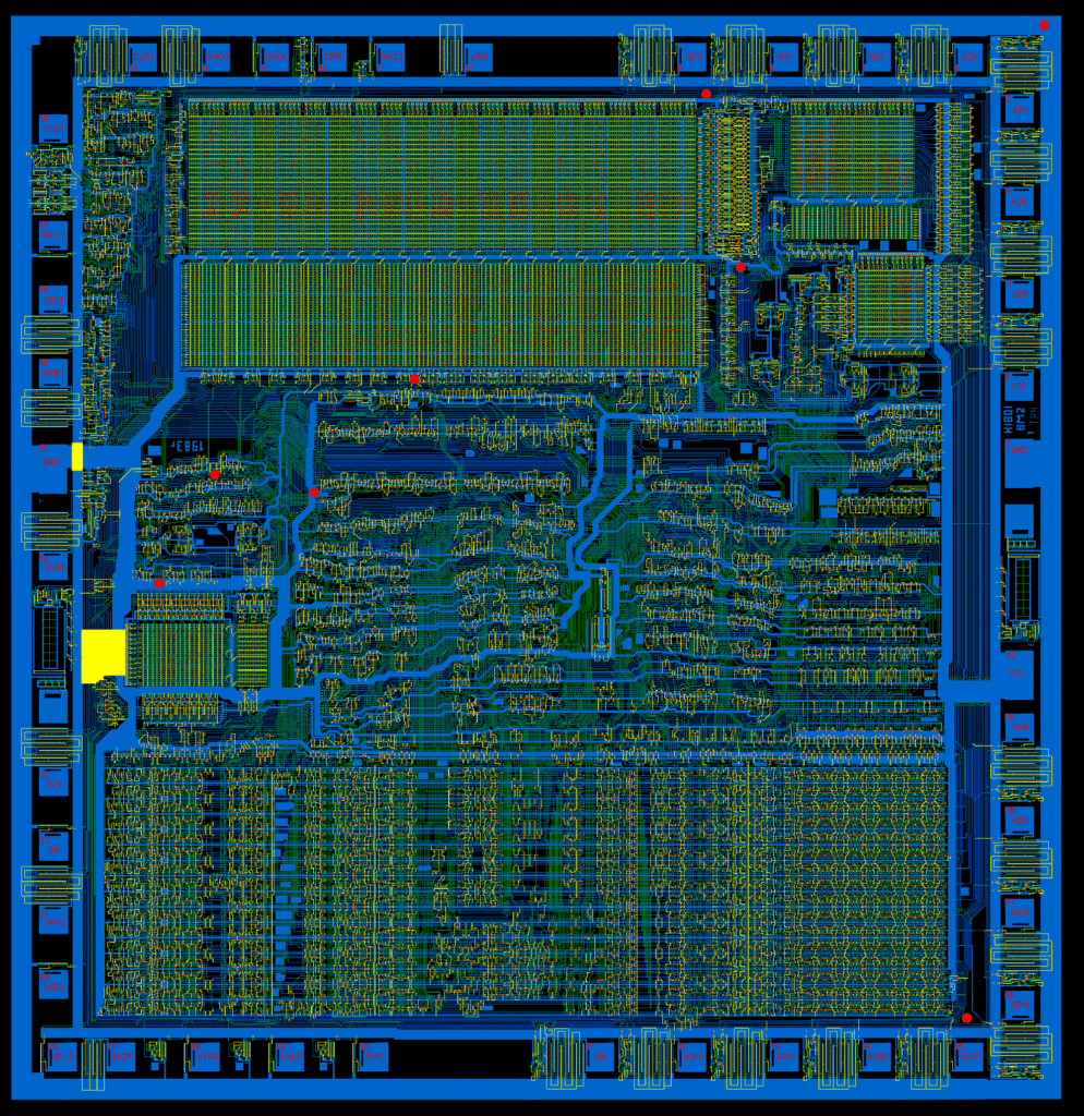
1801VM2 die

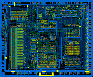
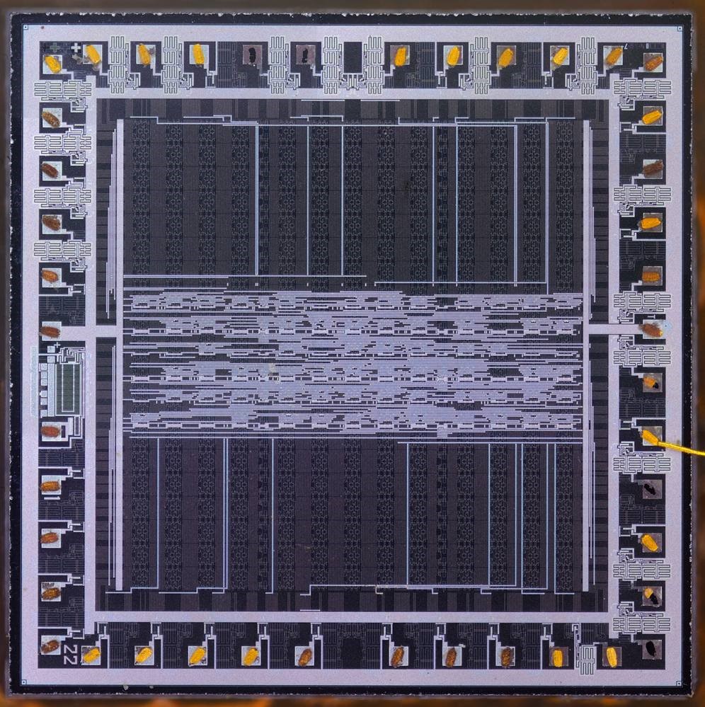
1801VM3 Die

1801VM3 Specifications

  • Number of processor Instruction: 72 Fixed Point and 46 Floating Point (with 1801VM4 FPU)
  • Address Space: 4MB
  • General Purpose Registers: 8
  • Manufacturing process: 4 micron N-channel silicon gate MOS technology (later migrated to 3 micron)
  • Die size 6.65 × 8 mm
  • Transistor count: 28,900 active transistors, 200,000 integral elements
  • Clock rate: 4MHz  (1801VM3V) 5MHz (1801VM3B) 6MHz (1801VM3A, upgraded to 8 in 1991)
  • Performance: For register based operations (like addition) up to 1,500,000 instruction/s (1.5 MIPS)
  • IRQ Lines: 4
  • Supply voltage + 4.75V-5.52V
  • Power consumption: 1.7-2 W
  • Packages: CDIP64 (KM1801VM3) LQFP64 (KA1801VM3) CQFP64 (KN1801VM3/N1801VM3)

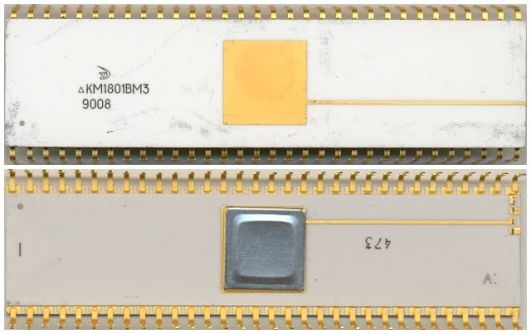
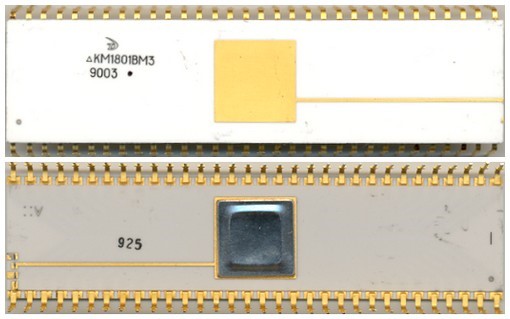
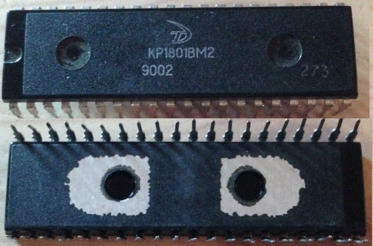
Like the VM2 before it the speeds were denoted by a series of dots on the package (or lack thereof)
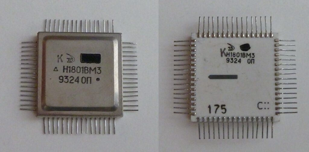
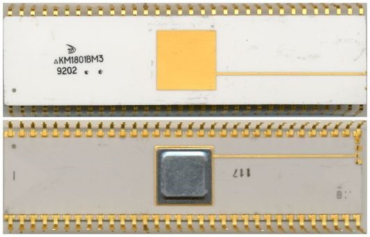
KM1801VM3A – 6MHz (no extra dot) CDIP64 package from 9008

KM1801VM3B – 5MHz (one extra dot) CDIP64 package from 9003

KM1801VM3V – 4MHz (two extra dots) CDIP64 package from 9202


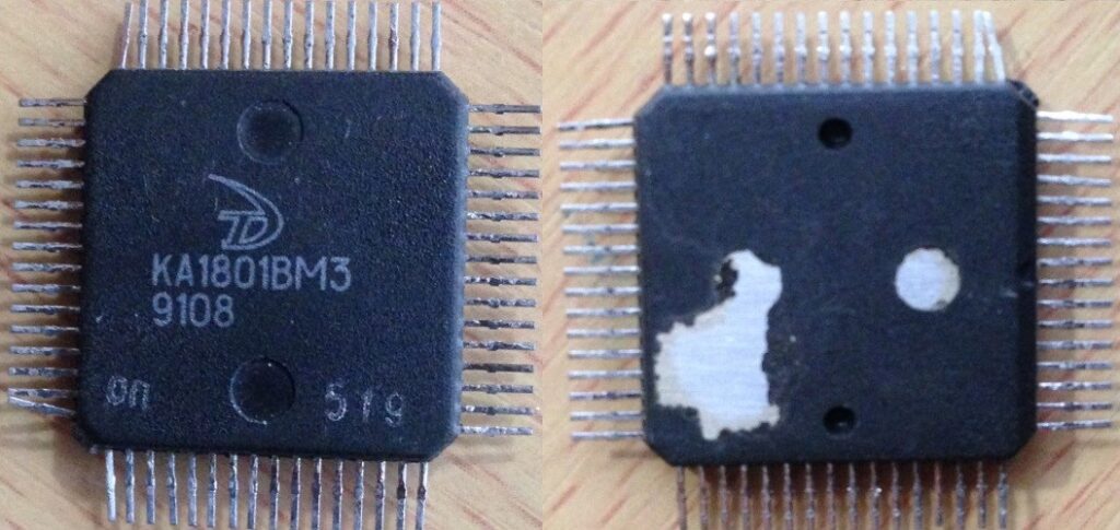
KA1801VM3 – 8MHz (no extra dot – post 1991) PQFP64 package from 9108

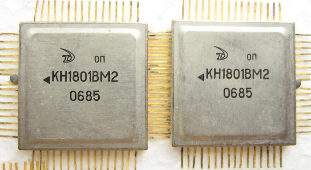
N1801VM3 – 8MHz (no extra dot – post 1991) CQFP64 package from 9324 – Remarked from a military part (rhombus marking marked over)


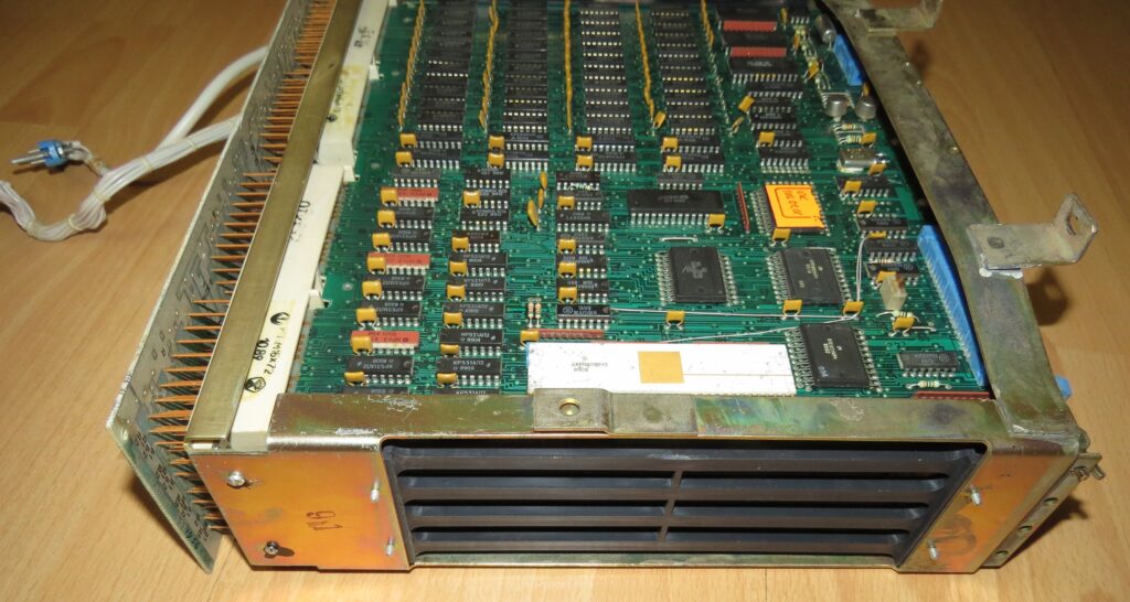
The KM1801VM3 appeared as part of the DVK line of computers, starting with the DVK-3M model (PCB ”Electronics МС 1201.03” and “Electronics МС 1201.04”).  Using the same ISA (Instruction Set Architecture) allowed DVK (and others) to rapidly update their computer line when new processors were available, and allow for a wider software base.  This is very much like the original IBM PC using the x86 architecture.  The transition from 8086 to 80286 was relatively easy to design, and nearly seamless for the end user.

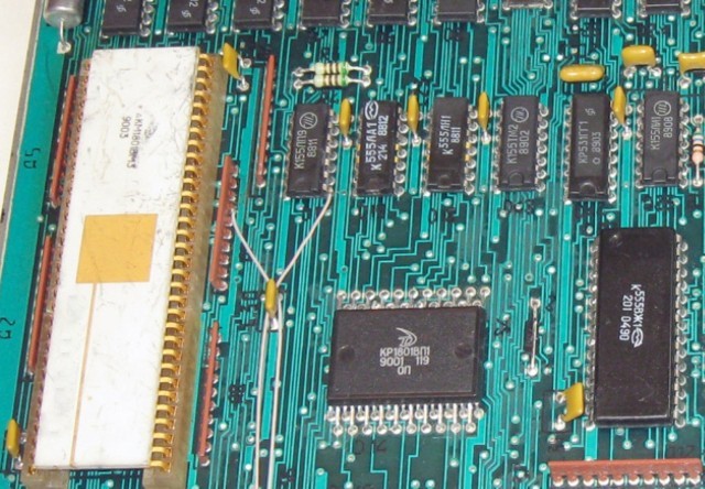
DVK PCB Electronics МС 1201.03 board on the top.

Many devices built on the basis of the 1801 series CPU contain other microcircuits of the same series (support circuits).
In addition to microprocessors, this series includes:
– ULA 1801VP1-xxx
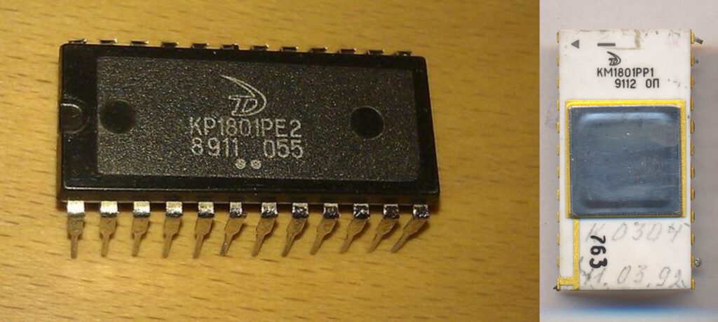
– masked ROM 1801REх-xxx
– EEPROM 1801RR1

ULA and EEPROM

The 1801VP1-xxx is a ULA- (Uncommitted Logic Arrays). It’s made using a 3 micron N-channel silicon gate MOS technology with one metal layer. First, base silicon wafers are made that contain transistors. These are doped regions of silicon and a separate oxide-insulated layer of polysilicon gates. Then all this is covered with an oxide layer. Base wafers are ready.

In this form, the wafers can be stored for a long time or transferred to another fab. All 1801VP1-xxx chips, regardless of number, have the same structure and arrangement of transistors. And they are made on the same base wafers.

KR1801VP1-22 die

Differences between the chips appear only at the last stage of manufacturing. In the upper oxide layer, the die is etched by photolithography to access the required transistors. And then form a metallic pattern from aluminum. This pattern defines the electrical circuit. The number in the marking identifies the purpose of the chip. For example, 1801VP1-033 is an external device controller.  This is similar to how a MaskROM is made but instead of only memory elements, it contains logic elements allowing for a custom IC to be made (like a mask programmable PAL/GAL)

KR1801VP1-119

The 1801VP1-119 is a companion chip for 1801VM3. It can be said to be the “north bridge“.
The 1801VP1-119 performs the following functions:
-forms control signals for DRAM;
-forms control signals for system SRAM;
-generates signals to select system ROM;
-generates control signals for detection and correction of memory errors (EDC) using Hamming code (555VGH1). Error correction circuits reduced performance by 10-15%. Therefore in some computers, there were jumpers to enable/disable the EDC
-buffer data register control;
-generate other signals

This was the beginning of what would be come chipsets, replacing loads of TTL with custom circuits.  The exact same evolution was occurring in the west with the PC environment, until nearly all the support circuits were integrated into just a couple large ASICs.   Its interesting to see the development paths of the Soviet computers and the West.  While they were entirely different instruction sets, they evolved in very much the same way.  East or West, LSI-11 or x86, at the end of the day, a computer is a computer and will evolve in similar fashion.


Posted in:
CPU of the Day

November 4th, 2021 ~ by admin

The Soviet 1801VM2 LSI-11 Processor

The Soviet-made 1801VM2 CPU (a binary-compatible implementation of the PDP11 instruction set and QBUS interface) was developed in 1982. The 1801VM2 is a further development of the earlier 1801VM1 doubling the original 5MHz clock speed. From a constructive standpoint this CPU is a completely independent development.

1801VM2 die

1801VM2 die – 1983 dated

1801VM2 Specifications

  • Number of processor Instruction: 72
  • Manufacturing process: 4 micron N-channel silicon gate MOS technology
  • Die size 5.3 × 5.35 mm
  • Transistor count: 18,500 active transistors, 120,000 integral elements
  • Clock rate: Up to 10 MHz
  • Performance: For register based operations (like addition) up to 1,000,000 instruction/s (1 MIPS) – for operations like multiplication, up to 100,000 instructions/s
  • Supply voltage + 5V
  • Power consumption: up to 1.7 W
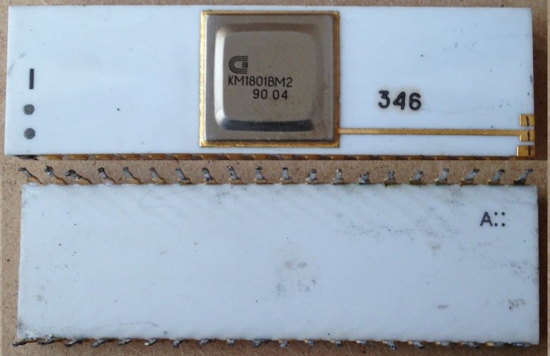
  • The case is 40-lead, ceramic DIP (KM1801VM2) or plastic DIP (KR1801VM2). (a surface mount version was also made)

To increase noise immunity in comparison with 1801VM1, additional ground contacts were made for the address / data bus.
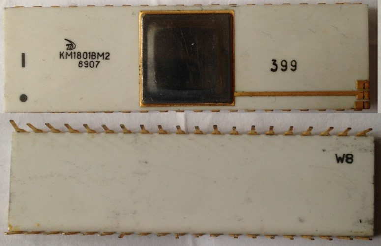
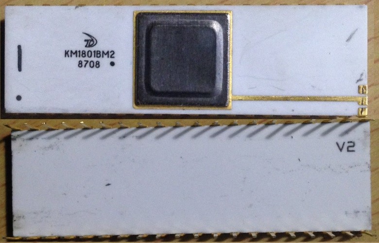
The 1801VM2 was manufactured at two factories: Angstrem and Solnechnogorsk Electromechanical Plant (SEMZ).  As was typical of the time speed grading was done by adding extra marking to the chips post-testing.  Its very easy to miss these, if a chip was tested at 10MHz and passed it received no extra marking and was considered an 1801VM’A.’  If the device failed at 10MHz but ran at 8MHz a small dot was added to the package (and was considered a grade ‘B’ device).  This dot was not to be confused with the dot for the pin one marker, though often placed…next to it.

Ceramic DIP 1801VM2A Angstrem – 1989 No extra dot

Ceramic DIP 1801VM2B Angstrem – 1987 – Note the extra dot in this case by the date code

Plastic DIP 1801VM2A Angstrem – 1990

KN1801VM2- Angstrem 1985 CQFP Surface mount version (image Baator)

Ceramic DIP 1801VM2 Solnechnogorsk Electromechanical Plant – 1990 – Extra dot by pin 1 marker

In comparison with 1801VM1, expanded arithmetic instructions (MUL, DIV, ASH, ASHC – part of a the set of PDP-11 EIS), and also operations from the floating point instruction set (FIS) were added. The FIS instructions (FADD, FSUB, FMUL, FDIV) are realized through subroutines – when performing these instructions there is a special type of interrupt and the program handler in memory (“shadow” system ROM K1801RE2) of the console mode is executed, a ‘firmware’ style of FIS implementation, as its not truly hardware (the ROMs break down the FIS instructions into something the 1801VM2 can execute)
During the design of the microprocessor, a microcode error was made, leading to a malfunction of the processor when reading with addressing method 17 ( MOV (PC), R0).

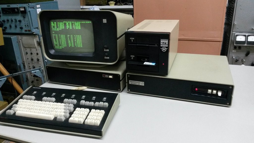
DVK-1 Computer

The 1801VM2 was the heart of a number models of DVK computer. DVK was developed at the Research Institute of Precision Technology , Zelenograd (just outside of Moscow). The first model DVK-1 was developed in 1981, and released in 1983. Architecturally DVK copies mini-computers from DEC PDC-11 and PDP-11. By 1990, 200,000 DVK computers of the nine different models were produced.

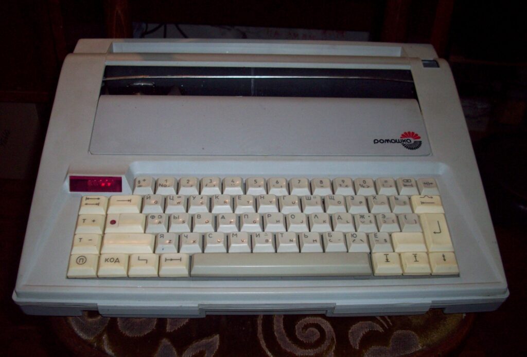
Romashka Word Processor

Use of the processor continued well into the 1990’s. The “Romashka” belonged to the latest generation of electronic typewriters, which in their functionality were close to computer text editors. This typewriter made it possible to automatically format text (set alignment, change the spacing between characters and between lines, use bold and underlined fonts, etc.) and had an electronic memory of at least one page (3800 bytes).  In the West these half typewriter half computer were called Word Processors, and were quite popular through the 1980’s.   The machine’s control unit was a microcomputer based on the KM1801VM2 processor.
“Romashka” was produced by the Kursk PO “Schetmash” in the first half of the 1990s.

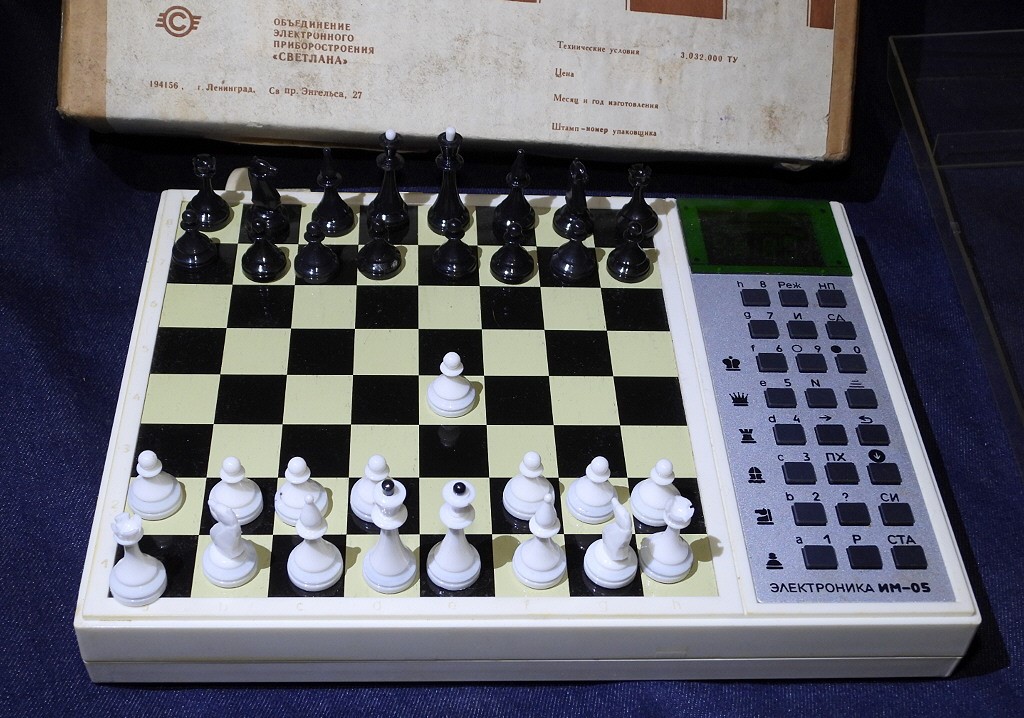
“Electronics IM-05 “- Soviet chess computer, contains 1801VM2 inside. It was a continuation of the line of chess computers “Electronics”. Produced by the Svetlana Association, Leningrad.

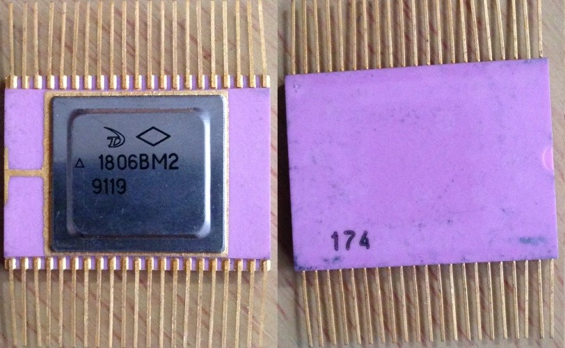
In 1984, the military-grade microprocessor 1806VM2 was released.
This microprocessor functionally corresponds to the 1801VM2, but is made using CMOS technology.

  • Clock rate: up to 5 MHz
  • Number of Instructions: 77
  • Contains 134,636 integral elements
  • Power consumption: up to 0.025W

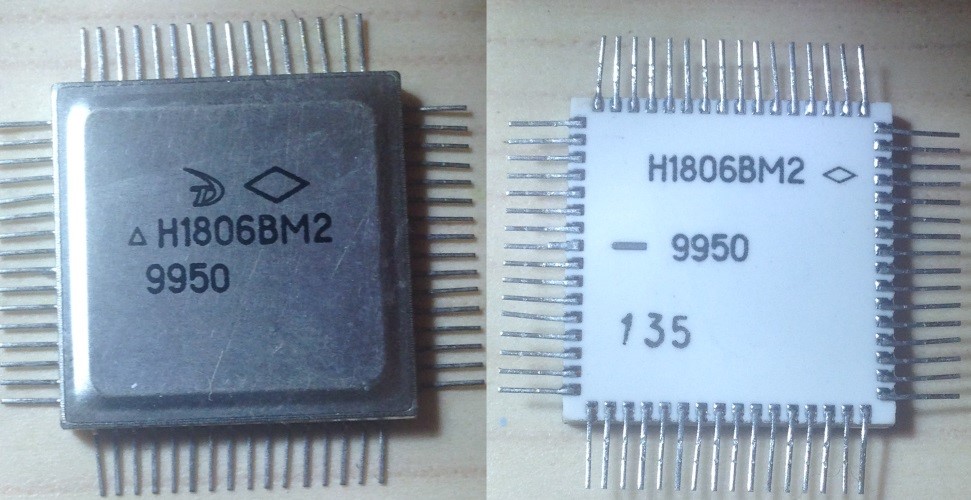
The 1806VM2 developers fixed the microcode bug present in 1801VM2 (much to the relief, or annoyance of programmers). The 1806VM2 was supplied in a 42-lead dual in-line ceramic package with flat leads, N1806VM2 in a 64-lead CQFP. The rhombus marking on the chips denotes a military-grade device.

1806VM2 – Angstrem 1991 in the nice pink flat pack

N1806VM2 – Angstrem 1999 in a Ceramic quad flat pack

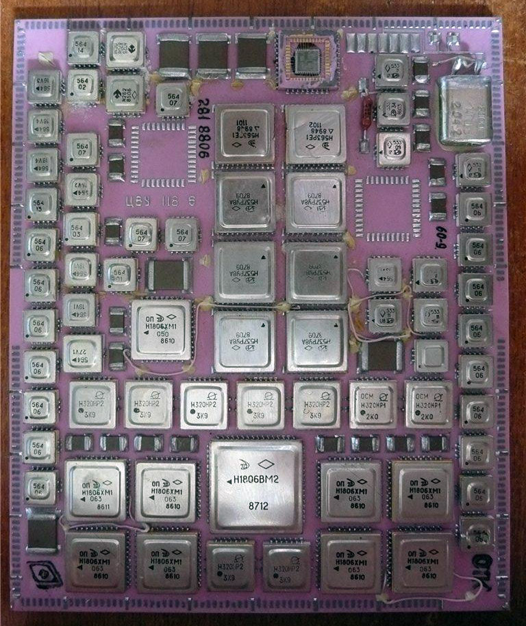
CQFP N1806BM2 on a ceramic substrate forming a military Single Board Computer – circa 1987 (image Baator)

These 1806VM2 are still being made by Angstrem, if you need to build a PDP-11 computer to run Tetris on, or repair a Buran shuttle you may have laying around.

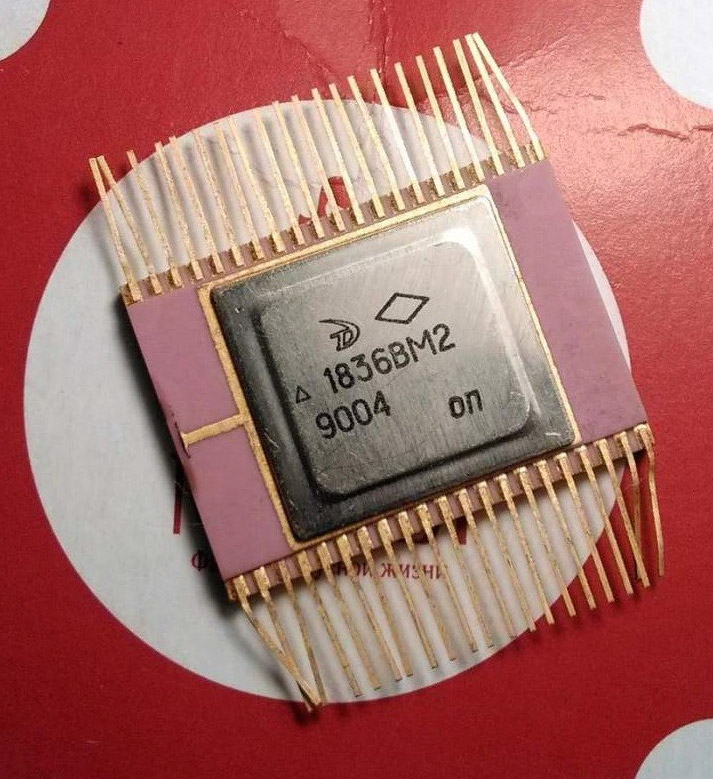
In 1990, a radiation-hardened microprocessor was introduced, compatible with the 1806VM2, known as the 1836VM2/N1836VM2.  Just like in other countries, existing code base and known reliability are more of a driver of what the military/industry uses than having the latest and greatest.  There are still MIL-STD-1750A processors being made and used, rad-hard 8051s and 80186s, and Soviet PDP-11 processors right there with them.

Photos of microprocessors from the collection of Perfiliev Andrey (Andreycpu).
Article written originally by Contributing Author Vladimir Yakovlev (edited by cpushack)

Posted in:
CPU of the Day

April 16th, 2020 ~ by admin

DEC M7260 KD11-A CPU: The PDP-11 Goes MSI

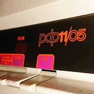
PDP-11/05 Front Panel (pic from vintage_electron)

Back in 1972 DEC released the ‘budget’ PDP-11/05 16-bit computer.  The original PDP-11/20 had been released 3 years before and its CPU (the KA11) was based on simple TTL, its ALU could perform adds and that was all, which meant its designers had to get creative in implementing the instruction set.  By 1972 however things had changed, there still was no 16-bit processors available but there was now single chip 4-bit ALU’s.  The ALU was the famous 74181 and formed the heart of the KD11-A, DEC’s 4th processor design (the ‘third’ was the KB11-A which was similar but based on the faster 74S181 and used in the PDP-11/45 and released at the same time) .

The KD11-A consisted of a pair of boards, the M7260 Data Path Module and the M7261 Control Logic and Microprogram Module.  All the processor functional components are contained on these modules. The M7260 Data Path Module contains: data path logic, processor status word logic, auxiliary arithmetic logic unit control, instruction register and decoding logic, and serial communications line interface. The M7261 Control Logic and Microprogram Module contains: internal address detecting logic, stack control logic, Unibus control logic, priority arbitration logic, Unibus drivers and receivers, microbranch logic, microprogram counter, control store logic, power fail logic, line clock, and processor clock.   The M7260 was he brain, and the M7261 told it what to do, containing the microcode to implement the PDP-11 instruction set.  This was the first version (with the 11/45) of the PDP-11 that was microcoded.

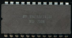
Fairchild 934159 74181 MSI 4-bit ALU made on a Bipolar – This example from very early 1971

The KD11-A ran off a single 150ns clock resulting in a raw clock speed of 6.67MHz, however performance was limited by memory access speed. The PDP-11/05 supported up to 32K Words (64KB) of core memory and this memory could only run at a 980ns cycle time.  This limited the 11/05 performance to around 1MHz.  This was still quite good for 1972!.

The 74181 was capable of running at 42MHz (and 90MHz for the 74S181 Schottky TTL versions) but in a set of 4 this drops to about 27MHz (with the carry generator taking some time).   Speed, however, is usually limited by other things rather then the ALU itself.   The 74181 ALU contains the equivalent of 62 logic gates (170 transistors) and can perform 16 different arithmetic and logic functions on a pair of 4-bit inputs.  Ken Shirriff did an excellent die level analysis of a ‘181 thats worth reading.  It includes pretty pictures even.

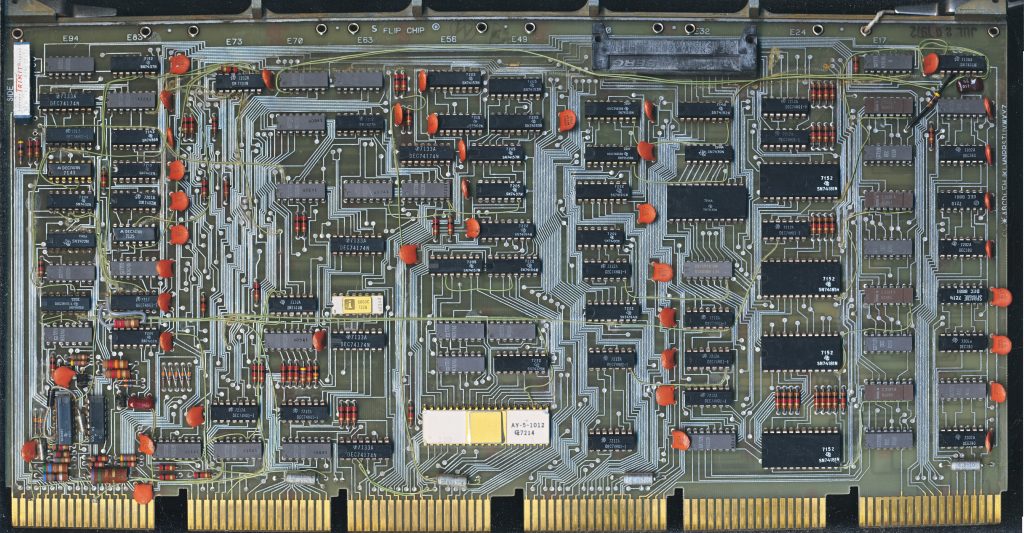
DEC M7260 – Data Path for the KD11-B CPU – Dated July 1972

This particular KD11-A board is one of the very first made.  It is dated July 20th 1972, a month after the initial release of the 11/05.  The big white chip is a General Instruments AY-5-1012 UART.  To its right you can see thr 4 74181 ALUs.  Each is 4-bit and together they form a complete 16-bit ALU for the CPU. A 74150 Multiplexer helps determine what data goes where.  The 74182 is the Look ahead carry generator for the ‘181’s.  Most of the rest of the chips on the board are ROMs and supporting logic.  There is also 4 Intel C3101A 35ns SRAM chips, these are 16×4 SRAMs used as scratch pad memories and only were used in the very first version of the CPU (later versions replaced them with cheaper 7489 TTL versions).  The Scratch Pad Memory is what forms the registers for the CPU.  There are 16 16-bit registers with the the first 6, R0-R5 being general purpose registers and the rest special purpose such as the Program Counter, Interrupt Vector, etc.

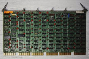
M7261 Control module – Contains the microcode for the CPU (pic from xlat.livejournal.com)

Another interesting point on this board is the very large amount of green wires running on the board.  These are called ECO wires, which are ‘Engineering Change Order’ wires, and are placed, by hand, after the board is made to correct faults in the board layout.  The goal is to not have these as they are expensive and delicate and can result in failures down the road, so further revisions of the board would have these fixed/implemented in the PCB.  You do not see these much at all any more as modern design/testing tools virtually eliminate the possibility of a faulty PCB layout making it into production.

When it was released the ~1MHz 11/05 cost $25,000, which in 2020 US Dollars is around $154,000.  THe PDP-11 series ended up being one of the most popular minicomputers, selling over 600,000 units over the years.  Later versions like the LSI-11 series moved the entire CPU to a single LSI chip, adding Extended Instructions, Floating Point Instructions, faster memories and other performance enhancements well into the 1980’s.   It was also widely comied, and enhanced in the Soviet Union and Russia.  It was on a Soviet PDP-11 clone that Tetris was developed, a game we are all rather familiar with.

Its amazing to see where computers have come in the span of but a few decades. but these important parts of history continue to be used.  Perhaps not the 11/05, but there are many PDP-11 systems still working away, typically inindustrial environments, ironically helping produce things likely far more advanced then themselves.

Posted in:
CPU of the Day
September 6th, 2015 ~ by admin

The Electronika MK1 red3 PDP-11 Chipset and Tetris

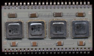
Soviet Electronika MK1red3 - F-11 Clone and implementation of PDP-11

Soviet Electronika MK1red3 – F-11 Clone and implementation of PDP-11

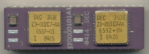
The DEC F-11 ‘Fonz’ implementation of the PDP-11 was released in 1979 and was DEC’s second ‘LSI’ implementation of the PDP.  Like its predecessor it was a multi-chip implementation, consisting at its root of a data chip (DC302) and 1-9 control chips (DC303).  The DC303 control chips were essentially a large ROM/PLA with a few extra features added for interrupts and sequencing.  They formed the microcoded instruction set that drove the 16-bit ALU and registers of the DC302.  This is why more then one were supported.  Expanding the instruction set was as ‘simple’ as adding more DC303 chips with these instructions encoded.  The basic LSI11/23 came with one 303 and one 302.  A second IC could be added to support floating point, which included a pair of DC303 chips implementing the floating point instructions.  A MMU (DC304) was also supported, and required when using the FP option.

DEC 570000101A1 F11 Floating Point Option with 2x 303E Control chips

DEC 570000101A1 F11 Floating Point Option with 2x 303E Control chips

The Soviets also widely adopted the PDP-11 architecture.  Likely because it was designed to be rather hardware independent.  It could be implemented in many different ways, which meant the Soviets could adopt/implement it on their own.  Electronika was part of the Soviet industrial complex in Voronezh, Russia making many different IC’s, but also was tasked with making consumer devices (computers and calculators etc, that were in very short supply.  The Electronika 60 was one of the first PDP-11 computers they made, and it implemented a copy of the DEC Fonz processor.  Electronika combined the standard chipset, and FPU onto a single large MCM with all 4 IC’s (the MMU remained separate) called the MK1 red1 (and later the MK1 red3)

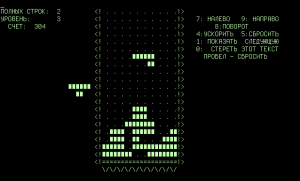
Tetris Electronika 60 - Text Only

Tetris Electronika 60 – Text Only

KH1811VM1 = DC302 – 21-15541 Data Chip (16-bit ALU etc)
KH1811VU1 = DC303 – 23-001C7 standard instruction set
KH1811VU2 = DC303 – 23-002C7 FP instruction set Part 1
KH1811VU3 = DC303 – 23-003C7 FP instruction set Part 2

It was on this chipset, on a Soviet Electronika 60 that Alexey Pajitnov wrote the very first version of the still famous game of Tetris back in 1984.  A game that was very popular, and very widely copied in the West, even to this day.  (the copying of technology most certainly went both ways)

Tags:
, , ,

Posted in:
CPU of the Day
November 21st, 2014 ~ by admin

When a Minicomputer becomes a Micro: the DGC microNOVA mN601 and 602

DGC logoThe late 1960’s and early 1970’s saw the rise of the mini-computer.  These computers were mini because they no longer took up an entire room.  While not something you would stick on your desk at home, they did fit under the desk of many offices.  Typically there were built with multiple large circuit boards and their processor was implemented with many MSI (medium scale integration) IC’s and/or straight TTL.  TTL versions of the 1970’s often were designed around the 74181 4-bit ALU, from which 12, 16 or even 32-bit processor architectures could be built from.  DEC, Wang, Data General, Honeywell, HP and many others made such systems.

By the mid-1970’s the semiconductor industry had advanced enough that many of these designs could now be implemented on a few chips, instead of a few boards, so the new race to make IC versions of previous mini-computers began.  DEC implemented their PDP-11 architecture into a set of ICs known as the LSI-11. Other companies (such as GI) also made PDP-11 type IC’s.  HP made custom ICs (such as the nano-processor) for their new computers, Wang did similar as well.

Data General was not to be left out.  Data General was formed in 1968 by ex DEC employees whom tried to convince DEC of the merits of a 16-bit minicomputer.  DEC at the time made the 12-bit PDP-8, but  Edson de Castro, Henry Burkhardt III, and Richard Sogge thought 16-bits was better, and attainable.  They were joined by Herbert Richman of Fairchild Semiconductor (which will become important later on.)  The first minicomputer they made was the NOVA, which was, of course, a 16-bit design and used many MSI’s from Fairchild.  As semiconductor technology improved so did the NOVA line, getting faster, simpler and cheaper, eventually moving to mainly TTL.

Read More »

Posted in:
CPU of the Day
October 11th, 2010 ~ by admin

Soviet Beauties: Processors from behind the Iron Curtain

The Soviet Union’s electronic programs were mainly focused on copying and cloning Western devices.  Either by simple theft, or painstaking reverse engineering.  They made clones of devices such as the Intel 8080, and the AMD 2901 as well as simple TTL.  The Soviets also made many single and multi-chip versions of the venerable DEC PDP-11 computer system.  Many of these have no Western analogs, they were pure creations of the Soviet industry.

Soviet Kvantor 580VM80 - Intel 8080 - Milspec

While Western chips rapidly transitioned into mostly black plastic by the 1980s the Soviets did not.  The 8080 above was made in 1991 though looks like something from the 70’s. Black plastic is cheap, and easy to make, but it isn’t great looking. The Soviets on the other hand made some of the best looking (if not always functioning) processors of the time.

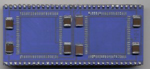
Soviet J-11 Missing the chips

Here is just the substrate (its a non finished example) of a Soviet clone of the DEC J-11 CPU. Not often do you see a brilliant blue processor.

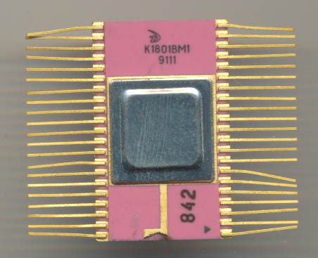
Soviet Angstrem K1801VM1

This is a nice pink ceramic Soviet PDP-11 5MHz CPU. Again this was made in 1991.  Its a form of surface mount package that was used extensively for industrial and military designs.  Just as the PDP-11 was used by the American military throughout the 70’s and 80’s. the Soviets used it (and now Russians) in todays times.

Soviet era CPUs are very interesting to collect.  Each state run factory had their own logo which was typically (but not always) put on the chip. Many part numbers were made by more then one factory. Most chips have a western analog, but not all.  Soviet chips also were ever so slightly different sized then Western ones. The Soviets used a pin spacing of 2.5mm where as the West used 0.1″ (2.54″), rather noticeable on a 40 pin DIP. Reading/translating some of the Cyrillic  based characters can be a chore but really when you get to see things like this…

Electronika J-11 - Image courtesy of iguana_kiev

Can you really complain?