How do you test a S3 GPU? With an HP 93000
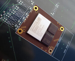
GammaChrome XM18 – Engineering Sample
Recently I got in some very nice S3 GammaChrome GPUs. The GammaChrome was S3 (owned by VIAs) follow on to the DeltaChrome and included support for such things at PCI-E. The S18 (Code name Brooklyn) supported speeds of up to 500MHz and was made on a 130nm process by TSMC. S3 also made a mobile version of the S18 called the XM18 (Code name Metro MPM) in 64MB and 32MB versions. Clock speed on these was around 350MHz (memory on the samples I have is 350 so core should be similar). The XM18 was packaged on a MPM (Multi Package Module) with 2 RAM chips and the GPU mounted on a small chip size BGA with around 800 balls. This is very similar to how ATI packaged some of their mobile GPUs (like the Mobility Radeon 7500 and 9600).
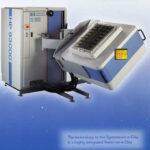
HP 93000 (from HP Brochure)
So how do you test one of the XM18 Engineering Samples? Or any large scale chip for
86C813 ES Gamma Chrome XM18 ULP MPM64
that matter? With Automated Test Equipment. ATE systems are designed to rapidly test various chips to verify their design/performance before they go into full production (or to test samples of production ones). The HP/Agilent 93000 (spunoff as Verigy in 2007 and acquired by Advantest Corporation in 2011) was introduced in 1999 to handle such testing, and at the time was rather revolutionary. Previously most test systems used a simple test head that would mount the chip to be tested, with all the processing and customizations being contained in the main test machine. This worked fine for a single design, but to test multiple chips got pretty expensive. HP moved the testing to the test head directly, interfacing to the target chip via a large PCB. This way changing chips only required updating the test program, and changing out the PCB. Design changes required reworking a single PCB, rather then the entire test machine.
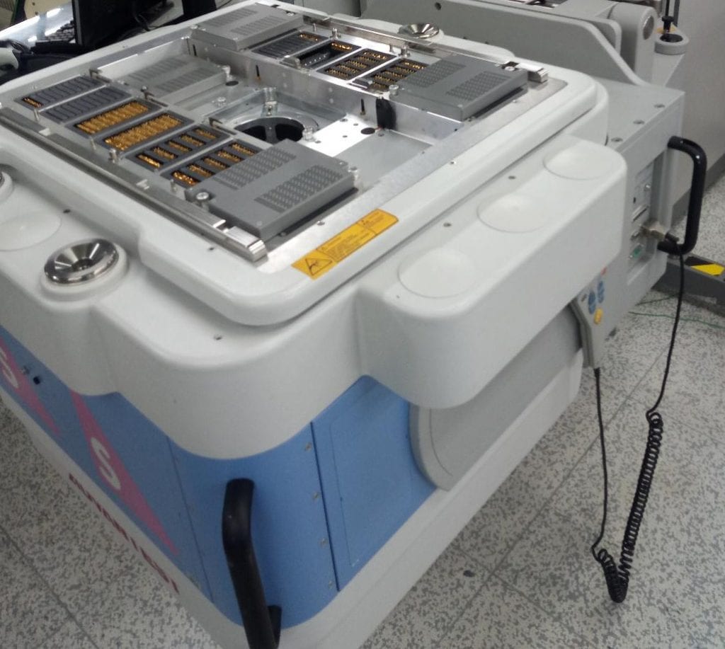
HP 93000 Test Head – Notice the 16 groups of pins (some covers and some mangled in this old sale photo)
The 93000 was the first ATE that achieved (on its low end (200Mbps) a cost of $1000/pin tested, and on the high end, test speeds of up to 1250Mbps (for the P1000 version, at a cost of $6-7000 per pin). The XM18 has around 800 pins, half are probably power/ground so 400 some odd testable pins, in a mid range HP 93000 and you see these systems were not inexpensive. Well over a million dollars for a midrange system.
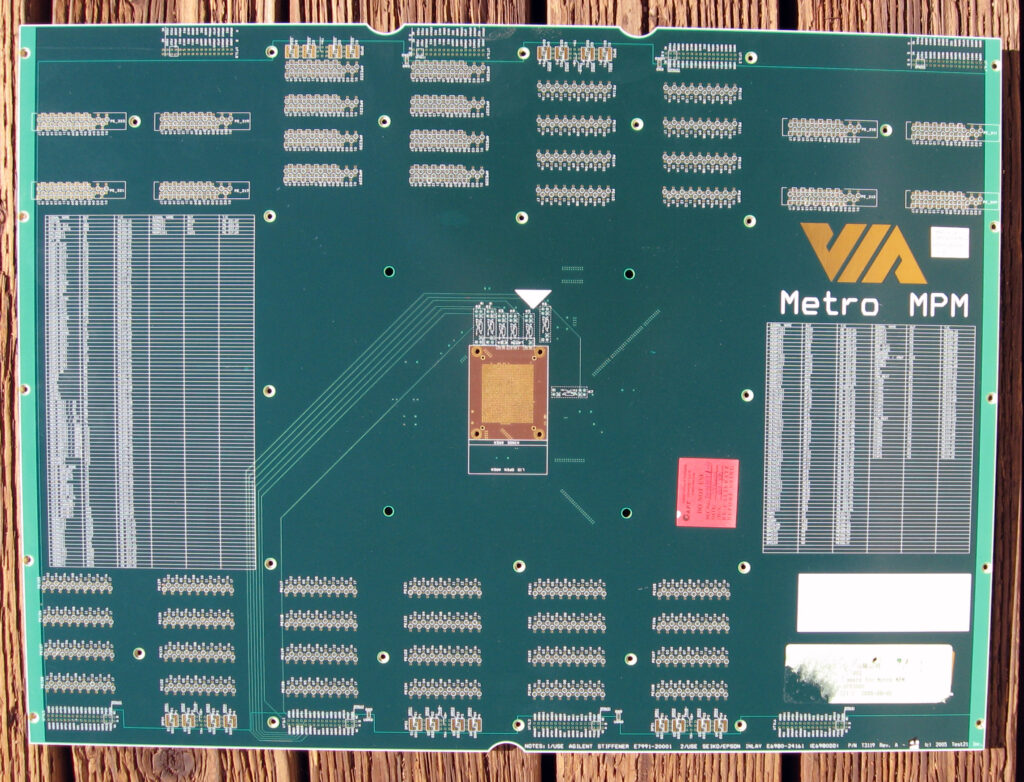
GammaChrome XM18 – Metro MPM Test Board
To use such a system the chip to be tested would be mounted on the test board, usually with a BGA socket. This board breaks out all the various connections of the chip to 16 sets of contacts, which the probe head of the HP 93000 made contact with using spring loaded contacts. The board is then clamped down and tests are run.
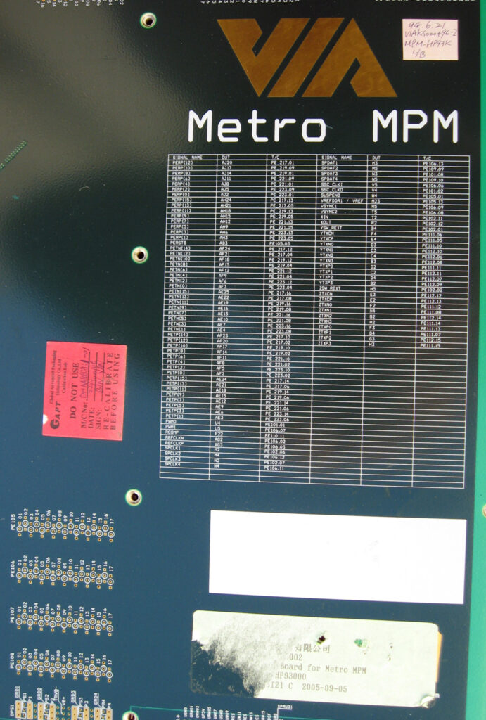
Connection List
These boards are very very large, each one is 17x23inches (43x58cm) and 5mm thick. They weigh about 7lbs (3.1kg) as well. They got used a lot and need to be rather robust and durable. You can see the boards are marked with tables of all the connections, and where they are brought out to. Useful information about what supporting equipment is need (sockets and stiffeners etc) is marked on the board as well.
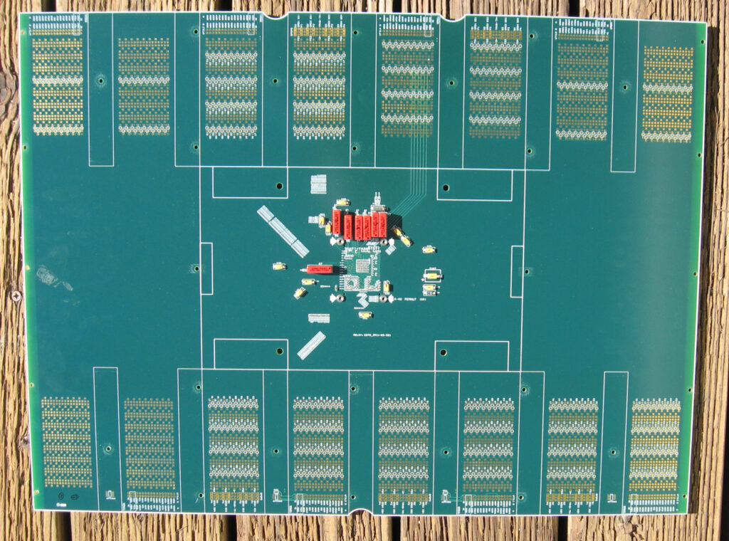
Back of board. Notice all the capacitors, a crystal, and a series of 5VDC reed relays (the red devices)
These boards appear to be a ‘static’ type item, but they do require adjustment, notice the markings that say not to use this board, it needs recalibrated. Looking closely at the board you can see capacitors have been removed/replaced, and many of the capacitors have felt tip marker markings on them. Keeping the capacitance and inductances at their proper values 9and matched, considering the long trace lengths) would be a very important thing.
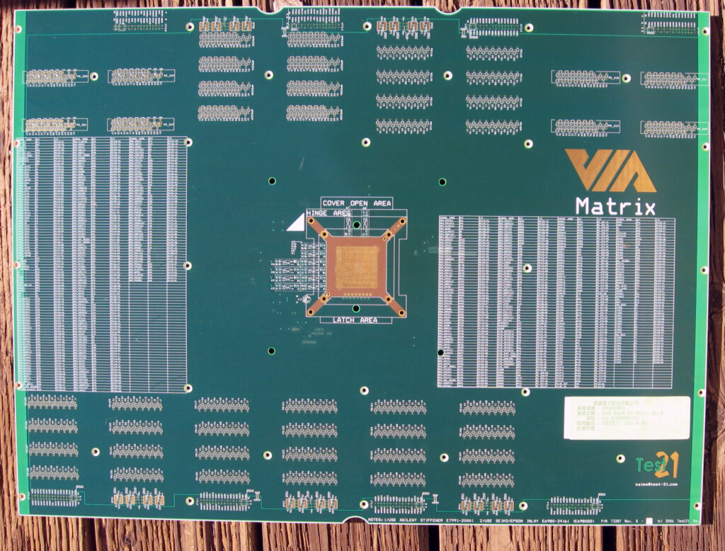
S3/VIA Matrix Test Board. The Matrix was the code name for the GammaChrome S14/S19
These test boards are from 2006, the 93000 systems are still being used today in upgraded form (now called the V93000) to test SoCs and other chips. As chips have gotten more and more complex, faster, and with larger pin outs, test equipment continues to grow ins peed, and cost as well, but is an essential part to the process of designing, producing and supporting a successful GPU or CPU.
Posted in:
Boards and Systems


