EPROM's have been a critical component to computers
for over 30 years. An EPROM is an erasable memory device that can
store a small amount of data. There are two common uses for EPROM's.
One is for storing a program, usually a simple program like the
BIOS in a computer or the application that runs a microcontroller.
The second use is a LUT, or a Look Up Table. A LUT is useful when
a set of known inputs values has one output value. For example,
multiplication use to be a very slow operation for microcontrollers,
to speed it up, the MCU would output the two numbers to an EPROM
(as an address) and the data stored at that address would be the
result.
There are several different types of EPROM's:
They have several distinct features.
| UV-EPROM |
UV EPROM's are programmed at high voltages (usually 28V)
and are erased by shining Ultra-Violet (high energy) light
at them through a window. They have no limit to read cycles
and can store data for over 20 years. |
| OTP |
One Time Programmable ROMS are generally identical to UV-EPROM's
with one exception, they do not have the window for UV light
and thus are not readily erasable.
This was done to save money, as they could be packaged in
a plastic package instead of ceramic/glass.
There has been some success in erasing these using X-Rays. |
| EEPROM |
These are Electronically erasable. Again it requires a higher
voltage (12.5V-28V) which can be generated on chip by a charge
pump. Write times are usually rather slow and power requirements
are hard to manage as writes take MUCH more power then reads.
EEPROM's also have a limited number of write cycles due to
electron tunnel oxide degradation, a result of quantum mechanics. |
| Flash |
Flash is very similar to EEPROM's except they are built
to write/erase entire blocks (multi-byte) at a time (EEPROM
writes a byte at a time). This makes writes faster, and saves
transistors. |
We're going to concentrate on UV-EPROM's in this article as they
are more historical these days.
(however the concept and physics is mostly the same)
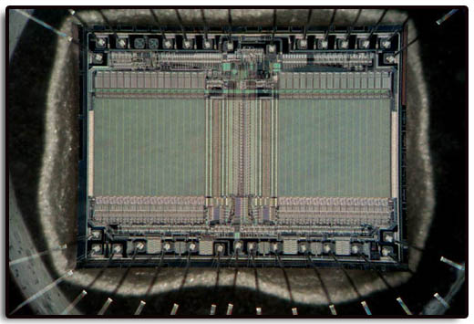
An EPROM is a large array of Floating
Gate Transistors.
Inside a floating gate MOSFET, the main components are a control
gate, floating gate, and the thin oxide layer. The EPROM has a
grid of columns and rows and the cell at each intersection has
two transistors. The two transistors are separated from each other
by a thin oxide layer. One of the transistors is known as the
floating gate and the other as the control gate. The floating
gate's only link to the row (wordline) is through the control
gate. As long as this link is in place, the cell has a value of
1. To change the value to 0 requires a process called Fowler-Nordheim
tunneling. Tunneling is used to alter the placement of electrons
in the floating gate. An electrical charge, usually 10 to 28 volts,
is applied to the floating gate. The charge comes from the column
(bitline), enters the floating gate and drains to a ground.
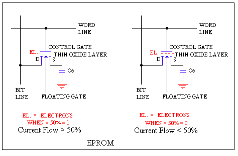
This charge causes the floating-gate transistor to act like an
electron gun. The excited electrons are pushed through and trapped
on the other side of the thin oxide layer, giving it a negative
charge. These negatively charged electrons act as a barrier between
the control gate and the floating gate. A device called a cell
sensor monitors the level of the charge passing through the floating
gate. If the flow through the gate is greater than 50 percent
of the charge, it has a value of 1. When the charge passing through
drops below the 50-percent threshold, the value changes to 0.
A blank EPROM has all of the gates fully open, giving each cell
a value of 1.
To rewrite an EPROM, you must erase it first. To erase it, you
must supply a level of energy strong enough to break through the
negative electrons blocking the floating gate. In a standard EPROM,
this is best accomplished with UV light at a wavelength of 253.7
nanometers. Contrary to popular belief, sunlight does not erase
your EPROM. Because this particular frequency will not penetrate
most plastics or glasses, each EPROM chip has a quartz window
on top of it. The EPROM must be very close to the eraser's light
source, within an inch or two, to work properly.
Too much UV-Light can excite the electrons TOO much resulting
in an 'over-erased' condition that cannot be readily be fixed.
OTP EPROM's just lack the window, so there is no way to get UV-Light
in them. Several individuals have gotten around this by using
X-Rays which is just a higher energy wave in the electromagnetic
spectrum. It WILL penetrate the plastic case and erase it, however,
since it is MUCH higher energy, it is easy to over-erase the chip.
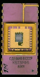
EPROM's are packaged in a ceramic package because of the embedded
quartz crystal. During normal heating and cooling cycles a Quartz/Plastic
package would fail. Ceramic and Quartz expand and contract at
the same rate making the ceramic package the only acceptable form.
This decreases failures but greatly increases cost. NOTE: Apparently the Soviets solved this, as I have 3 Soviet EPROM's that are in a plastic package. It appears to be all resin, with a small hole that has a resin lens planted in it.
History:
The first EPROM was the Intel C1701 back in 1971 which stored
256 bytes of information. Today's EPROM's hold 8Mb or more.
Below is a listing of most all Parallel EPROM's that were used.
These EPROM's have separate pins for Data and Address (non-multiplexed)
and take the data out in parallel. Modern day EPROM's now either
multiplex the Address/Data ports or take the data out via a serial
connection (often I2C)
| EPROM |
Size (bits) |
Structure |
Pins |
Address Lines |
Picture |
| 1701 |
2k |
256 x 8 |
24 |
8 |
|
| 1702
- 4702
- 8702 - 5203 - 9702 - U552C |
2k |
256 x 8 |
24 |
8 |
 |
| 6601 - 6653 - 6603 |
4k |
1k x 4 |
24 |
10 |
|
2704 - 6654 - 6604 8704 - 5204
|
4k |
512 x 8 |
24 |
9 |
|
2708 - 8708 - 2758 - U555C - K573RF1 -2508
|
8k |
1k x 8 |
24 |
10 |
|
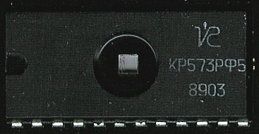
| 2716 - 2717 - 4716 - 2516 - K573RF2 - K573RF5 - 27291 - 27245 |
16k |
2k x 8 |
24 |
11 |
 |
| 8755 |
16k (w/ IO) |
2k x 8 |
40 |
11 |
|
| 2732 - 2532 |
32k |
4k x 8 |
24 |
12 |
|
| 2764
- 8764 -2763 - 2564 - 57C49 - 68766 K573RF4 - K573RF6A |
64k |
8k x 8 |
28 |
13 |
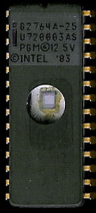 |
| 27128 |
128k |
16k x 8 |
28 |
14 |
|
| 27256 - 87256 - 87257 |
256k |
32k x 8 |
28 |
15 |
|
| 27512 - |
512k |
64k x 8 |
28 |
16 |
|
| 27513 |
512k |
4 x 16k x 8 |
28 |
14 |
|
27010, 27101, 27100, 27301,
271000 - 271001 - 2710000 - 571001 |
1024k |
128k x 8 |
32 |
17 |
|
| 27011 |
1024k |
8 x 16k x 8 |
28 |
14 |
|
| 271024 - 27102 - 27210 - 571024 |
1024k |
64k x 16 |
40 |
16 |
|
| 272001 - 27201 - 27020 |
2048k |
256k x 8 |
32 |
18 |
|
| 272048 -27202 - 27220 |
2048k |
128k x 16 |
40 |
17 |
|
27040 - 274001
27401 |
4096k |
512k x 8 |
32 |
19 |
|
| 274096 - 274002 - 27402 - 27240 |
4096k |
256k x 16 |
40 |
18 |
|
| 274100 - 27400 - 274000 |
4096k |
512k x 8
256k x 16 |
40 |
18-19 |
|
| 27801 - 27080 - 278001 |
8192k |
1024k x 8 |
32 |
20 |
|
| 278000 (Micronix) |
8192k |
1024k x 8 |
32 |
20 |
|
| 27800 - 278000 |
8192k |
1024k x 8
512k x 16
|
42 |
19-20 |
|
| 27160 |
16384k |
2048k x 8
1024k x 16 |
42 |
20-21 |
|
| 27332 |
32768k |
2048k x 16 |
42 |
21 |
|
| 27642 |
65536k |
4096k x 16 |
42 |
22 |
|
| Notes |
|
| 27Cxxx - |
CMOS part (as opposed to NMOS |
| 87xxxx - |
Denoted latched address, for use with multiplexed MPUs (like
the 8086) |
| 27LV or 27V |
Low Voltage Parts (3V - 3.6V Supplies) |
| 27Hxxx |
Hispeed access times |
| 27Wxxx |
used by several companies to denote 2.7V compliant parts |
| 47xx |
Used for the MCS-4 Computer set |
| 97xx |
AMD Version of the MCS-80 EPROM's (for the Am9080 etc) |
| 57xxx |
Common Toshiba prefix |
UV-EPROM's are at the end of their life. Newer technologies are
smaller, cheaper, and faster. These chips served us well into
the 21st Century, impressive for a technology that is over 30
years old. They will continue to serve in many control applications
until old equipment is replaced.
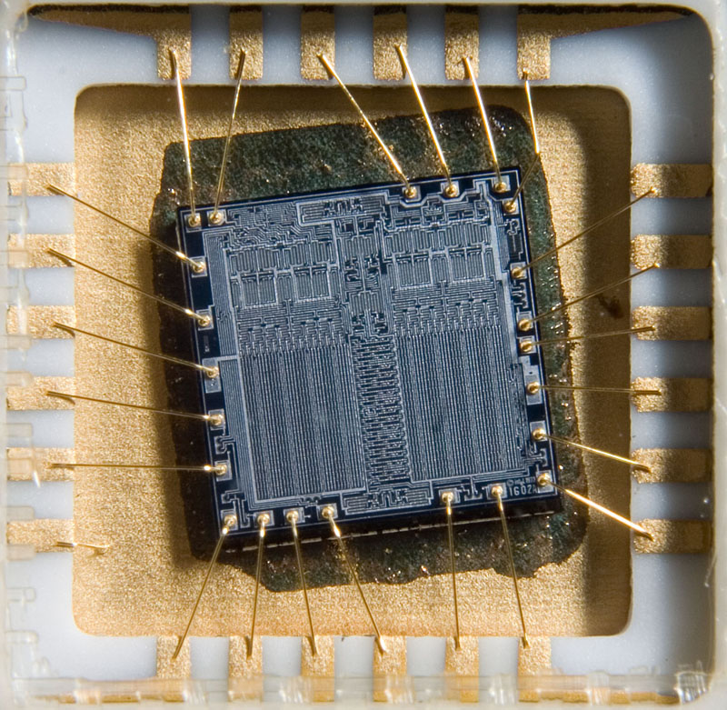
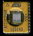
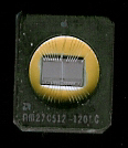
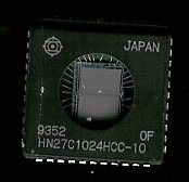
(image courtesy of MrLaptop)
|